Meta Description: A technical guide to selecting the right casting material for heavy industrial applications. Compare carbon steel, stainless steel, and ductile iron on mechanical properties, corrosion resistance, cost, and industry-specific performance requirements.
Every casting project begins with a single critical question: which material? The answer determines not only the part's in-service performance but also the casting process feasibility, machining strategy, heat treatment requirements, and ultimately the total cost of ownership. Yet material selection is often reduced to a cursory comparison of tensile strength and price — a mistake that can cascade into premature failure, warranty claims, and production downtime.
This technical guide provides a structured, engineering-level comparison of the three most widely specified material families for heavy industrial castings: carbon steel, stainless steel, and ductile iron. We examine their metallurgical foundations, mechanical behavior, processing characteristics, and real-world application profiles to equip engineers and procurement professionals with a rigorous selection framework.
Understanding the fundamental differences between these three material families begins with their chemical and microstructural identities.
Carbon steel is an iron-carbon alloy where carbon is the primary alloying element, typically ranging from 0.15% to 0.60% by weight. The carbon content directly governs hardenability, strength, and weldability:
| Grade (ASTM) | Carbon % | Tensile Strength (MPa) | Yield Strength (MPa) | Elongation (%) | Typical Use |
|---|---|---|---|---|---|
| WCB (A216) | 0.25 max | 485–655 | 250 min | 22 min | General-purpose valves, pump casings, structural castings |
| WCC (A216) | 0.25 max | 485–655 | 275 min | 22 min | Higher-strength valves and fittings |
| LCB (A352) | 0.30 max | 450–620 | 240 min | 24 min | Low-temperature service to -46 °C |
| LCC (A352) | 0.25 max | 485–655 | 275 min | 22 min | Low-temperature service to -46 °C, higher strength |
| 8630 (A487) | 0.28–0.33 | 620–795 | 485 min | 17 min | High-strength structural, Cr-Mo-Ni alloy |
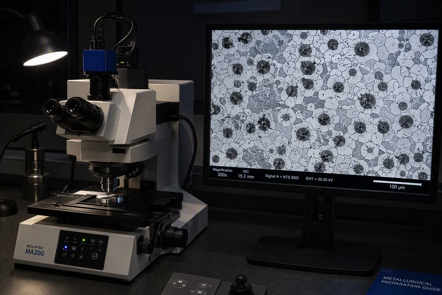
Microstructure: In the as-cast and annealed condition, carbon steels exhibit a ferrite-pearlite microstructure. With heat treatment (normalizing, quenching and tempering), the microstructure transforms to tempered martensite or bainite, dramatically increasing strength and hardness at the expense of some ductility.
Key characteristics:
Stainless steels contain a minimum of 10.5% chromium, which forms a self-healing passive chromium oxide layer on the surface. The three most commonly cast stainless steel families are austenitic, martensitic, and duplex.
| Grade (ASTM) | Key Alloying | Tensile (MPa) | Yield (MPa) | Elongation (%) | Corrosion Resistance |
|---|---|---|---|---|---|
| CF8 / 304 (A351) | 18Cr-8Ni | 485 min | 205 min | 35 min | Good general corrosion resistance |
| CF8M / 316 (A351) | 18Cr-10Ni-2.5Mo | 485 min | 205 min | 30 min | Superior pitting and crevice corrosion resistance; marine and chemical service |
| CF3 / 304L (A351) | 18Cr-8Ni, C ≤ 0.03 | 485 min | 170 min | 35 min | Low-carbon variant for welded fabrications; eliminates intergranular corrosion risk |
| CF3M / 316L (A351) | 18Cr-10Ni-2.5Mo, C ≤ 0.03 | 485 min | 170 min | 30 min | Low-carbon 316; preferred for as-welded chemical and marine equipment |
Microstructure: Fully austenitic (face-centered cubic crystal structure). This structure is non-magnetic, highly ductile, and does not undergo a ductile-to-brittle transition — austenitic stainless steels retain toughness down to cryogenic temperatures (-196 °C and below).
Key characteristics:
| Grade (ASTM) | Carbon % | Tensile (MPa) | Hardness (HRC) | Typical Use | |---|---|---|---|---|---| | CA15 / 410 (A487) | 0.15 max | 620–795 | 22–30 (Q&T) | Turbine blades, pump shafts, wear components | | CA40 / 420 (A743) | 0.15–0.40 | 690 min | 25–50 (Q&T) | High-hardness wear parts, cutlery, valve trim | | CA6NM (A487) | 0.06 max | 760–930 | 23–30 (Q&T) | Hydroelectric turbine runners, high-toughness requirement |
Microstructure: Martensitic (body-centered tetragonal) after quenching. Can be tempered to achieve a wide range of hardness and toughness combinations. Magnetic.
Key characteristics:
| Grade (ASTM) | Composition | Tensile (MPa) | Yield (MPa) | PREN | Typical Use |
|---|---|---|---|---|---|
| CD4MCu (A890) | 25Cr-5Ni-3Cu-2Mo | 690 min | 485 min | 33–36 | Pump casings, impellers, marine hardware |
| CE3MN / 2507 (A890) | 25Cr-7Ni-4Mo-N | 800 min | 550 min | 40–43 | Offshore, chemical process, desalination |
Microstructure: Approximately 50% austenite + 50% ferrite — combining the best properties of both phases.
Key characteristics:
Ductile iron (also called spheroidal graphite iron or nodular iron) is produced by treating molten gray iron with magnesium or cerium before pouring, causing the graphite to precipitate as spheroids rather than flakes. This microstructural difference is the single most important distinction between gray and ductile iron.
| Grade (ISO / EN) | Grade (ASTM) | Tensile (MPa) | Yield (MPa) | Elongation (%) | Hardness (HB) | Typical Microstructure |
|---|---|---|---|---|---|---|
| QT400-18 / GGG40 | 60-40-18 | 400 min | 250 min | 18 min | 130–180 | Fully ferritic |
| QT500-7 / GGG50 | 65-45-12 | 500 min | 320 min | 7 min | 170–230 | Ferrite-pearlite |
| QT600-3 / GGG60 | 80-55-06 | 600 min | 370 min | 3 min | 190–270 | Pearlite-ferrite |
| QT700-2 / GGG70 | 100-70-03 | 700 min | 420 min | 2 min | 225–305 | Predominantly pearlitic |
| QT800-2 | 120-90-02 | 800 min | 480 min | 2 min | 245–335 | Pearlitic or tempered |
Special grades:
| Grade | Key Feature | Application |
|---|---|---|
| SiMo ductile iron | 4–6% Si + 0.5–1.0% Mo | High-temperature exhaust components (manifolds, turbocharger housings) — service to 800 °C |
| ADI (Austempered Ductile Iron) | Austempered heat treatment | Tensile 900–1600 MPa with 1–10% elongation; gears, crankshafts, wear plates |
| Ni-Resist (D5, D5B) | 18–36% Ni | Cryogenic service, seawater corrosion, non-magnetic applications |
Microstructure: Graphite spheroids distributed in a ferritic, pearlitic, ferritic-pearlitic, or ausferritic matrix. The spheroidal graphite morphology eliminates the stress-concentration effect of flake graphite, giving ductile iron its characteristic combination of strength and ductility.
Key characteristics:
| Material | Tensile Range (MPa) | Yield Range (MPa) | Yield-to-Tensile Ratio | Design Implication |
|---|---|---|---|---|
| Carbon steel (WCB/WCC) | 485–655 | 250–275 | 0.49–0.52 | Significant plastic deformation before failure — forgiving in overload |
| Carbon steel (Q&T 8630) | 620–795 | 485–620 | 0.78–0.78 | High strength but less post-yield reserve |
| Austenitic SS (304/316) | 485–620 | 170–205 | 0.35–0.42 | Low yield-to-tensile ratio means large deformation at yield — excellent for seismic and pressure vessel design |
| Duplex SS (CD4MCu) | 690–800 | 485–550 | 0.69–0.70 | High static strength with adequate ductility |
| Ductile iron (QT500-7) | 500 | 320 | 0.64 | Competitive with carbon steel WCB at lower cost |
| Ductile iron (QT700-2) | 700 | 420 | 0.60 | Replaces cast and forged steel in many structural applications |
Design note: Yield-to-tensile ratio is a critical but often overlooked parameter. A low ratio (austenitic stainless) provides a large plastic deformation window before fracture — desirable for pressure-containing equipment and seismic-resistant structures. A high ratio (Q&T steels, duplex) indicates limited post-yield ductility and requires more conservative design margins.
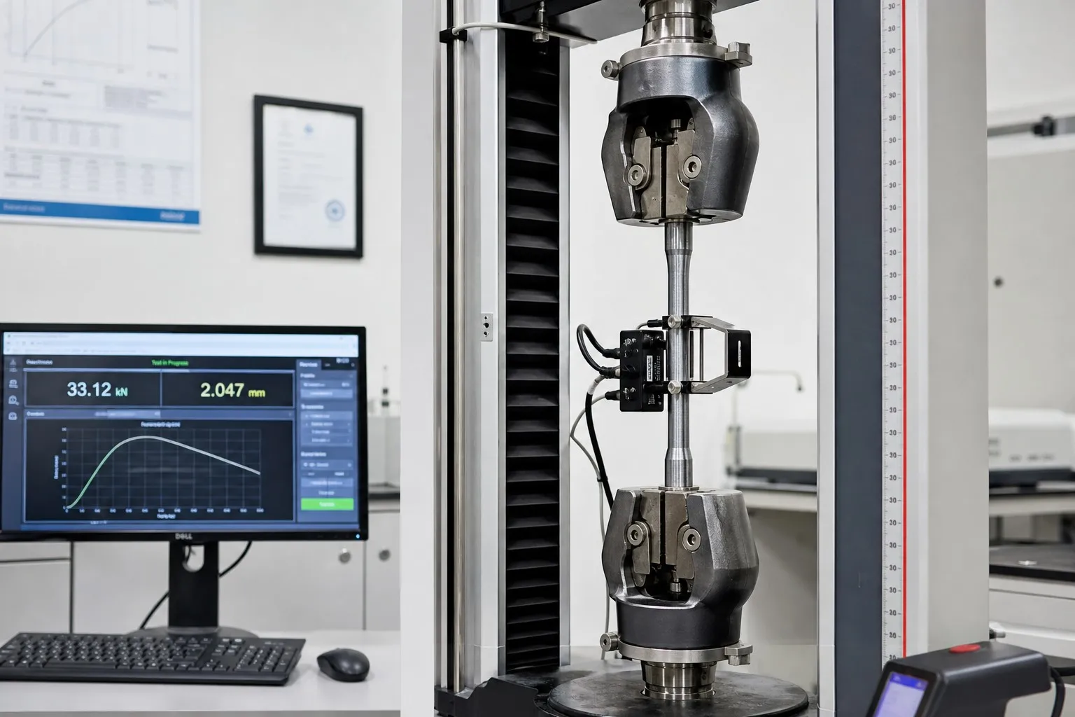
Fatigue is the most common failure mode in dynamically loaded cast components. The fatigue limit (endurance limit at 10⁷ cycles) varies significantly:
| Material | Fatigue Limit (MPa) | As % of UTS | Notes |
|---|---|---|---|
| Carbon steel (annealed) | 200–250 | ~40–45% | Ferrite-pearlite structure; clear endurance limit |
| Austenitic stainless (304) | 170–220 | ~35–40% | Work-hardens during cycling; no true endurance limit |
| Duplex stainless | 280–350 | ~40–45% | High strength translates to high fatigue limit |
| Ductile iron (QT500-7) | 180–220 | ~40–45% | Graphite nodules act as crack arrestors at low stress |
| ADI | 300–450 | ~30–40% | Exceptional fatigue resistance for an iron casting |
Ductile iron performs remarkably well in fatigue compared to cast steels at equivalent strength levels — a fact often underappreciated in design. The graphite nodules serve as crack-arrest features, slowing fatigue crack propagation.
This is where the material families diverge most dramatically and where incorrect selection has the most severe consequences.
| Material | Charpy V-Notch at 20 °C (J) | Charpy at -40 °C (J) | DBTT Range (°C) |
|---|---|---|---|
| Carbon steel WCB | 25–40 | 5–15 | -20 to +10 |
| Carbon steel LCB/LCC | 30–50 | 18–30 | -50 to -30 |
| Austenitic SS (304/316) | 100–200 | 80–160 | No DBTT — ductile to -196 °C |
| Duplex SS | 40–80 | 20–40 | -50 to -30 |
| Ductile iron (ferritic QT400-18) | 14–18 (at RT) | 10–14 | -40 to -20 |
| Ductile iron (pearlitic QT700-2) | 5–10 (at RT) | 2–5 | +10 to -10 |
Critical selection rule: For any application involving sub-zero temperatures, impact testing at the minimum design metal temperature (MDMT) is non-negotiable. This is codified in pressure vessel codes (ASME Section VIII, EN 13445) and piping standards (ASME B31.3). A material that meets tensile requirements at room temperature may fail catastrophically by brittle fracture at -20 °C.
Austenitic stainless steels are the only option when service temperatures drop below approximately -50 °C, as all ferritic and martensitic materials (including carbon steels, duplex, and ductile irons) experience a ductile-to-brittle transition.
| Environment | Carbon Steel | 304 SS | 316 SS | Duplex SS | Ductile Iron |
|---|---|---|---|---|---|
| Atmospheric (rural) | Poor — requires coating | Excellent | Excellent | Excellent | Poor — requires coating |
| Atmospheric (marine/coastal) | Very poor | Moderate | Good | Excellent | Very poor |
| Fresh water | Poor | Excellent | Excellent | Excellent | Moderate |
| Seawater | Not suitable | Marginal | Good | Excellent | Not suitable |
| Dilute acids (pH 2–4) | Not suitable | Marginal | Good | Good | Not suitable |
| Caustic (NaOH, pH 10–14) | Good to 80 °C | Good | Good | Good | Good |
| Chloride SCC risk | None | High above 60 °C | Moderate | Very low | None |
| H₂S (sour service) | Acceptable (NACE MR0175) | Acceptable (annealed) | Acceptable (annealed) | Acceptable (with hardness limit) | Not recommended |
For sour service (H₂S-containing environments in oil and gas), NACE MR0175/ISO 15156 imposes maximum hardness limits: 22 HRC for carbon and low-alloy steels, 28 HRC for duplex stainless steels, and 35 HRC for solid-solution nickel-based alloys in austenitic condition.
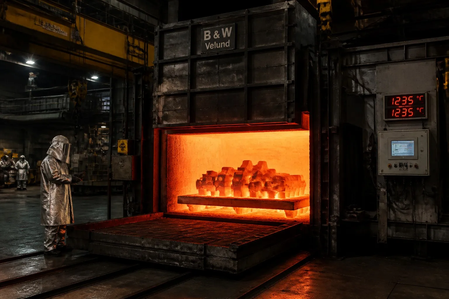
| Material | Max Continuous Service (°C) | Key Degradation Mechanism |
|---|---|---|
| Carbon steel | 400–450 | Graphitization of pearlite; oxidation above 500 °C |
| Austenitic SS (304) | 800–870 | Sigma phase embrittlement (565–925 °C range); oxidation above 900 °C |
| Austenitic SS (316) | 800–870 | Better oxidation resistance than 304; sigma phase embrittlement |
| Duplex SS | 280–300 | 475 °C embrittlement limits upper service temperature |
| SiMo ductile iron | 750–800 | Oxidation; ferrite grain growth; pearlite decomposition |
| Standard ductile iron | 350–400 | Pearlite decomposition; oxidation |
| Ni-Resist D5 | 800–850 | Oxidation; austenite stability at temperature |
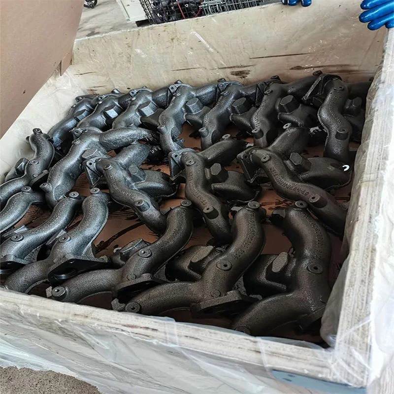
The SiMo exception: Standard ductile iron is unsuitable above ~400 °C due to pearlite decomposition and oxidation. However, SiMo ductile iron (4–6% Si, 0.5–1% Mo) forms a stable ferritic matrix with a protective silicon-rich oxide layer, enabling service at exhaust temperatures up to 800 °C. This makes it the material of choice for turbocharger housings and exhaust manifolds in commercial vehicles — a high-volume application where austenitic stainless steel or Ni-Resist would be cost-prohibitive.
| Material | Weldability | Filler Metal | Preheat | PWHT Required? |
|---|---|---|---|---|
| Carbon steel (C ≤ 0.25%) | Excellent | E7018 / ER70S-6 | 50–150 °C for thick sections | Yes (stress relief at 600–650 °C) |
| Carbon steel (C > 0.30%) | Moderate — cracking risk | E7018 / ER80S | 200–300 °C mandatory | Mandatory |
| Austenitic SS | Excellent | E308 / ER308 (304); E316 / ER316 (316) | None for thin sections | Solution anneal at 1040–1120 °C for SCC resistance; not always required |
| Martensitic SS | Difficult — requires strict control | E410 / ER410 | 200–350 °C mandatory | Mandatory (650–750 °C temper) |
| Duplex SS | Moderate — heat input critical | E2209 / ER2209 | None for thin sections | Not normally required (controlled heat input preserves phase balance) |
| Ductile iron | Difficult — special procedures | Ni-base (ENiFe-CI) or Fe-Ni (ENi-CI) | 300–400 °C mandatory | Slow cool from 600 °C |
Practical implication for foundries: The ability to weld-repair casting defects is a significant cost factor. Carbon steel castings with minor surface defects are routinely repaired by qualified welders following documented weld procedure specifications (WPS). Ductile iron casting defects, by contrast, are difficult to repair reliably and often result in scrapped castings — contributing to the higher rejection rate and effective yield loss of ductile iron compared to steel.
Cost comparison based on normalized raw material, melting, and processing costs (indexed to carbon steel WCB = 100):
| Material | Relative Cost Index | Primary Cost Drivers |
|---|---|---|
| Carbon steel (WCB/WCC) | 100 | Low alloy cost; simple melting; high yield |
| Carbon steel (low-alloy, Q&T) | 120–150 | Alloy surcharges (Cr, Mo, Ni); heat treatment cost |
| Ductile iron (ferritic) | 85–100 | Lower melting temperature; Mg treatment cost; higher rejection rate |
| Ductile iron (SiMo) | 110–130 | Ferro-silicon and ferro-molybdenum cost; specialized heat treatment |
| Austenitic SS (304/CF8) | 250–350 | High Ni and Cr content; AOD refining; slower melting; lower casting yield |
| Austenitic SS (316/CF8M) | 300–400 | Mo surcharge (currently $25–35/kg Mo); premium scrap required |
| Duplex SS | 350–500 | Tight chemistry control; narrow pouring window; higher scrap rate |
Total cost of ownership (TCO) caveat: The material cost per kilogram is only one component. A more corrosion-resistant material may eliminate the need for protective coatings and reduce lifecycle maintenance costs. Stainless steel pump casings in seawater service may have 3× the initial material cost but eliminate the annual recoating and corrosion allowance replacement that carbon steel casings require.
| Service Condition | Recommended Material | Rationale |
|---|---|---|
| Water, steam, oil up to 400 °C, non-corrosive | Carbon steel WCB/WCC | Economic optimum; well-characterized in pressure vessel codes |
| Sour service (H₂S) up to 200 °C | Carbon steel WCB (NACE MR0175, 22 HRC max) | Code-accepted; cost-effective with proper hardness control |
| Chemical process, acids, chlorides | CF8M (316) or duplex | Molybdenum provides pitting resistance; duplex for chloride SCC resistance |
| Cryogenic service (-50 to -196 °C) | CF8/CF8M (304/316) only | No DBTT; certified Charpy at MDMT |
| High-pressure (>Class 600) | Low-alloy steel (A487 Gr 4/6, 8630) | Higher strength reduces wall thickness, saving weight and cost |
| Component | Recommended Material | Rationale |
|---|---|---|
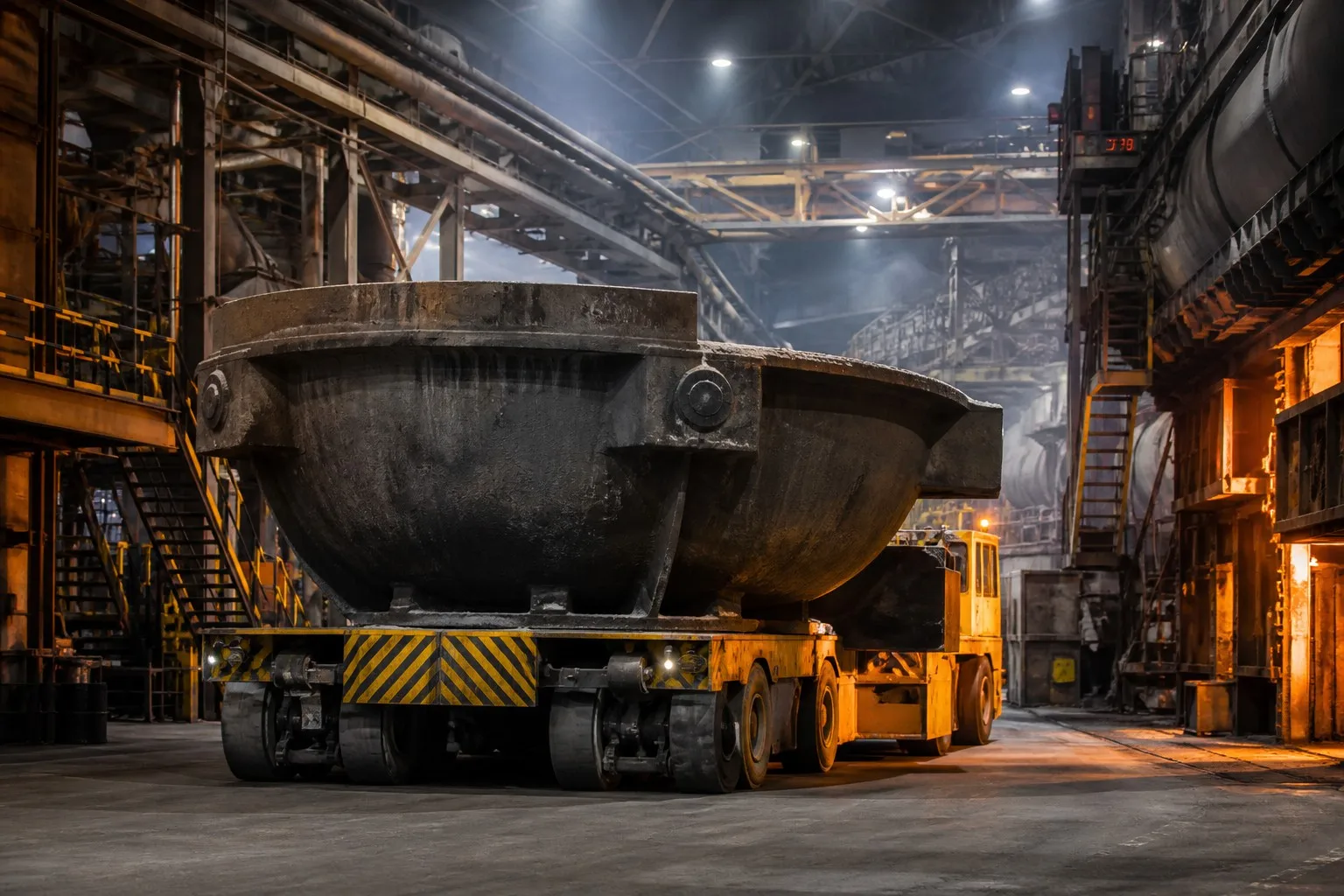
| Slag pot bodies | Carbon steel (modified WCB) or low-alloy Cr-Mo steel | Thermal fatigue resistance; weld-repairable; massive sections (5–25 tons) |
| Bucket teeth, crusher jaws | Austenitic manganese steel (Hadfield) | Extreme work-hardening capacity; unmatched wear resistance under impact |
| Crusher concaves and mantles | Martensitic Cr-Mo white iron or manganese steel | High-stress abrasion resistance |
| Structural frames, hitches | Carbon steel (WCB/WCC) or ductile iron (QT500-7) | Weldable; good fatigue resistance; cost-effective |
| Component | Recommended Material | Rationale |
|---|---|---|
| Exhaust manifold (diesel, <800 °C) | SiMo ductile iron (4–6% Si, 0.5–1% Mo) | Thermal fatigue resistance; oxidation resistance; cost-effective at volume |
| Exhaust manifold (gasoline, >900 °C) | Cast stainless steel (HK30, 20Cr-10Ni) or Ni-Resist D5S | Higher hot strength and oxidation resistance than SiMo |
| Turbocharger turbine housing | Ni-Resist D5S or cast stainless (HK30) | Cyclic thermal exposure to 950 °C; dimensional stability |
| Brake caliper | Ductile iron (QT500-7 or QT600-3) | Strength, machinability, damping, and cost |
| Steering knuckle | Ductile iron (QT600-3) or forged steel | High fatigue resistance; safety-critical component |
| Service | Recommended Material | Rationale |
|---|---|---|
| Fresh water, neutral pH | Ductile iron or carbon steel with coating | Economic selection; coating provides corrosion barrier |
| Seawater, brackish water | CD4MCu (duplex) or CF8M (316) | Chloride pitting resistance; duplex preferred for higher strength and SCC resistance |
| Chemical process, acids | CF8M (316) with corrosion allowance | Well-characterized in chemical service; wide range of compatible fluids |
| High-head, high-speed pumps | CA6NM (martensitic SS) or duplex | High strength-to-weight; cavitation erosion resistance; weld-repairable |
| Slurry pumps (abrasive service) | High-chrome white iron (25–28% Cr) for wet end; ductile iron for casing | Extreme abrasion resistance in wet end; ductile iron casing for pressure containment |
When specifying a material for an industrial casting, follow this structured decision sequence:
Document the full operating envelope before evaluating any material:
In most applications, one requirement dominates and narrows the material choice:
| Dominant Requirement | Narrows To |
|---|---|
| Sub-zero toughness below -50 °C | Austenitic stainless steel only |
| Chloride SCC risk | Duplex stainless steel or non-stainless with barrier coating |
| Extreme wear/abrasion | High-Cr white iron, manganese steel, or hardfaced carbon steel |
| High temperature (>800 °C) | Austenitic stainless, Ni-Resist, or SiMo (up to 800 °C) |
| Lowest cost, moderate conditions | Carbon steel or ductile iron |
| Magnetic permeability requirement | Carbon steel, martensitic SS, or ductile iron (austenitic SS is non-magnetic) |
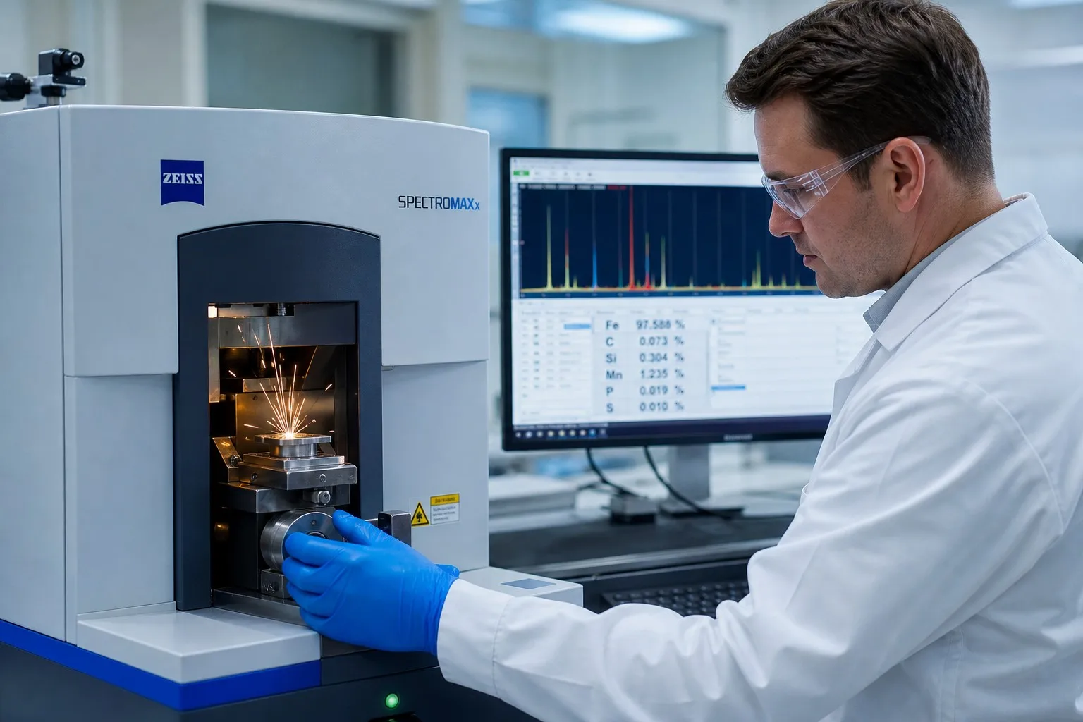
Specify the material to an established standard (ASTM, EN, ISO) that defines:
Request the applicable material certificate:
Drawing from decades of casting failure analysis, here are the patterns most likely to result in premature component failure:
"Make it out of stainless steel" is not a specification. Generic 304 (CF8) will fail rapidly in seawater through pitting corrosion — 316 (CF8M) or duplex is required. Conversely, specifying 316 where 304 would suffice adds unnecessary cost without any performance benefit.
Correct approach: Define the corrosion mechanism (uniform, pitting, crevice, SCC, intergranular) and specify the grade that addresses it.
A ductile iron gear housing that performs flawlessly in a Saudi Arabian desert installation may shatter on first impact at a Siberian mine site. Materials with a DBTT cannot be assumed ductile at low temperatures — impact testing at MDMT is essential.
Austenitic stainless steel expands approximately 17 × 10⁻⁶ /°C, while carbon steel expands at approximately 12 × 10⁻⁶ /°C. An assembly mixing both materials will develop thermal stresses during temperature cycling. Bolted flange joints are particularly susceptible — differential expansion can relax bolt preload or, conversely, overstress bolts.
The spheroidal graphite in ductile iron fundamentally changes its mechanical behavior compared to gray iron. Ductile iron has an elastic modulus of approximately 169 GPa (vs. 100–120 GPa for gray iron) and exhibits measurable ductility. Design rules, machining parameters, and welding procedures developed for gray iron do not transfer to ductile iron.
A carbon steel slag pot that costs 60% less than a low-alloy Cr-Mo alternative but lasts half as long before thermal fatigue cracking requires replacement is not the economic choice. Lifecycle cost analysis — including downtime, replacement labor, and lost production — should drive material selection for service-critical components.
| Priority | Carbon Steel | Ductile Iron | Austenitic SS | Duplex SS |
|---|---|---|---|---|
| Lowest initial cost | ✅ Best | ✅ Very good | ❌ High | ❌ Very high |
| Best machinability | ✅ Good | ✅ Excellent | ❌ Difficult | ❌ Difficult |
| Weldability (castings) | ✅ Excellent | ❌ Poor | ✅ Excellent | ⚠️ Moderate |
| Impact toughness at -40 °C | ⚠️ LCB/LCC only | ❌ Marginal | ✅ Excellent | ⚠️ Acceptable |
| Corrosion resistance | ❌ Requires coating | ❌ Requires coating | ✅ Good (316: better) | ✅ Excellent |
| High temperature (>600 °C) | ❌ Not suitable | ⚠️ SiMo only | ✅ Good | ❌ Embrittlement |
| Wear/abrasion resistance | ⚠️ Moderate | ✅ Good (graphite) | ❌ Poor (galling) | ✅ Good |
| Fatigue resistance | ✅ Good | ✅ Good | ⚠️ No endurance limit | ✅ Good |
| Damping capacity | ⚠️ Low | ✅ Excellent | ⚠️ Low | ⚠️ Low |
| Section thickness capability | ✅ Unlimited | ✅ Large | ✅ Large | ⚠️ Limited |
Legend: ✅ = Strong candidate; ⚠️ = Acceptable with conditions; ❌ = Not recommended
The "best" material does not exist in isolation — it is always the material that satisfies all mandatory requirements at the lowest total cost of ownership. A structured selection process, informed by metallurgical fundamentals and validated by material standards with appropriate testing, is the most reliable path to a successful casting specification.
Need expert guidance on material selection for your next casting project? Our engineering team provides material consultation, process feasibility analysis, and complete documentation support — from EN 10204 3.1 material certification through final dimensional inspection. Contact us to discuss your requirements.
 Hot News
2026-10-16
2026-10-09
2026-10-02
2026-09-25
2026-09-18
2026-09-11
Dandong City Pengxin Machinery was founded in 1958, is a set of casting, machining and assembly as one of the private enterprises.
Wangjiapu Group, Xinan Village, Qianyang Town, Donggang City, Dandong City, Liaoning Province, China
Copyright © Dandong City Pengxin Machinery Co.,Ltd. All Rights Reserved Privacy Policy Blog
 EN
EN