Meta Description: An in-depth engineering guide to turbocharger turbine and compressor housing casting. Learn alloy selection (SiMo, D-5S Ni-Resist, austenitic stainless steel 1.4837/1.4848, Inconel), shell mold coring for complex volute scrolls, 5-axis CNC machining, and burst testing.
Modern forced-induction engines operate under extreme thermodynamic duress. The turbocharger turbine housing is mounted directly to the engine exhaust stream, continually enduring pulsating thermal shock, corrosive exhaust gas chemistries, and continuous temperatures exceeding 850 °C in commercial diesels and up to 1,050 °C in high-performance gasoline engines. At the same time, the aerodynamic volute scroll must guide supersonic gas flow with micron-level precision to drive the turbine wheel without gas bypass or aerodynamic stall.
Manufacturing a turbocharger turbine housing or compressor housing is one of the most rigorous tests of a foundry’s metallurgical control, precision coring capability, and tight-tolerance CNC machining. A microscopic shrinkage void in the scroll tongue or a 0.03 mm concentricity error in the bearing cartridge bore leads directly to catastrophic turbocharger failure.
This comprehensive technical guide breaks down the metallurgical hierarchy, casting methodologies, tooling design, CNC machining strategies, and quality verification standards required to manufacture world-class turbocharger housings.
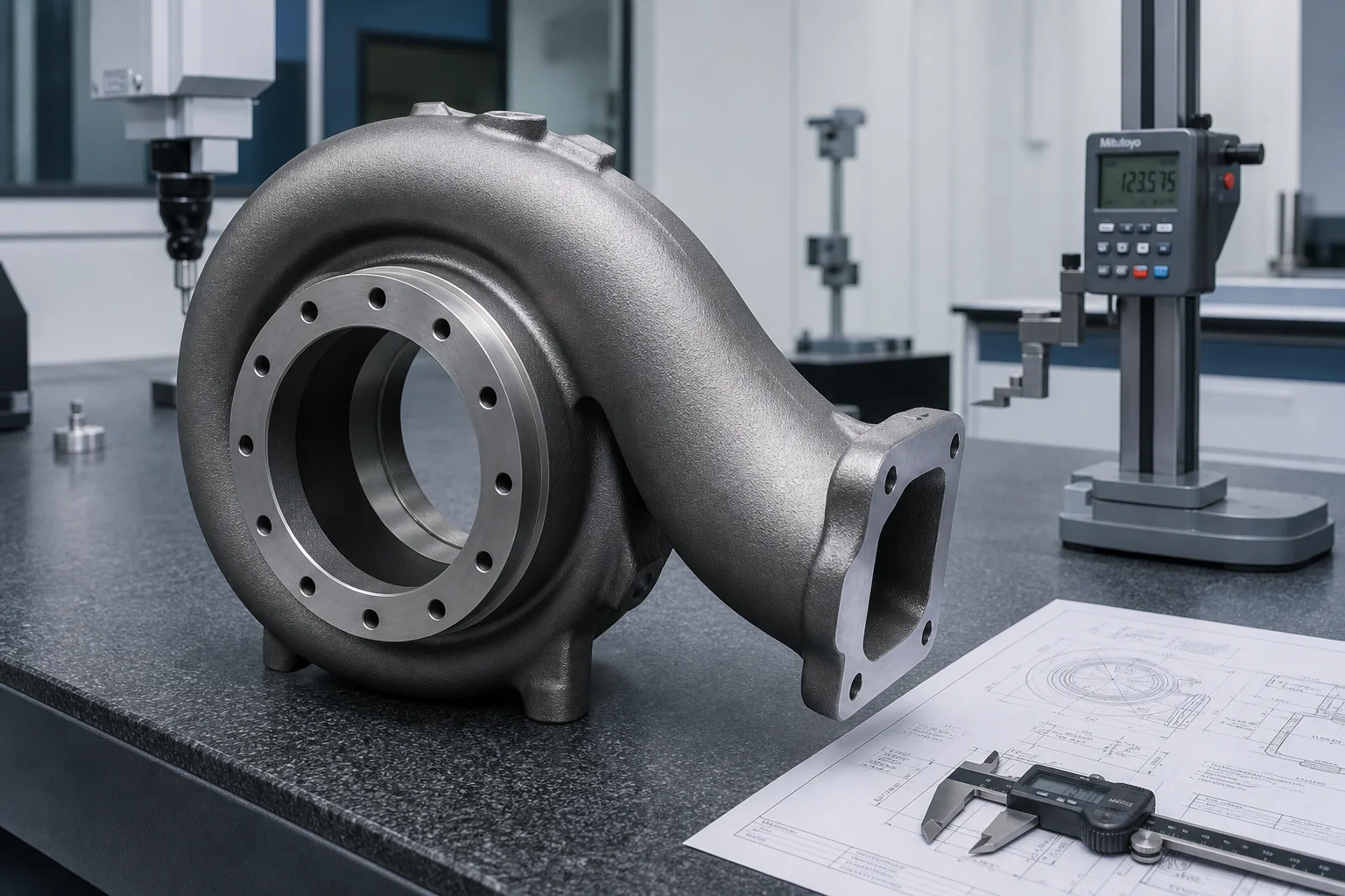
Turbine housings face combined mechanical and thermal stress fields that push conventional ferrous castings beyond their operational limits.
| Operating Parameter | Gasoline Turbochargers | Heavy-Duty Diesel Turbochargers |
|---|---|---|
| Peak Exhaust Gas Temp | 950 °C – 1,050 °C | 750 °C – 880 °C |
| Thermal Cycle Rate | Rapid acceleration/deceleration | Sustained high thermal load |
| Gas Pressure | Up to 4.0 bar (absolute) | Up to 5.5 bar (two-stage systems) |
| Rotational Speeds (Wheel) | 150,000 – 280,000 RPM | 90,000 – 160,000 RPM |
| Corrosive Species | Unburned hydrocarbons, NOx, sulfur | Soot particulate, acidic condensate |
Selecting the correct alloy is a direct balance between maximum service temperature, thermal fatigue resistance, machinability, and raw material cost.
| Alloy Family | Typical Standard / Grade | Max Continuous Temp | Key Metallurgical Mechanism | Relative Cost Index |
|---|---|---|---|---|
| Standard Ductile Iron | GGG40 / QT450-10 | 650 °C | Ferritic matrix; low high-temp oxidation resistance | 1.0 (Baseline) |
| Silicon-Molybdenum (SiMo) Ductile Iron | EN-GJS-SiMo40-6 / ASTM A874 | 820 °C | 4.0% Si raises ferrite transformation temp; 0.6% Mo increases creep rupture strength | 1.35x |
| High-Nickel Austenitic Iron (Ni-Resist) | D-5S / EN-GJSA-XNiSiCr35-5-2 | 920 °C | 35% Ni stabilizes austenitic structure; 5% Si provides dense protective silica scale | 3.2x |
| Cast Austenitic Stainless Steel | 1.4837 (GX40CrNiSi25-12) / HK30 | 980 °C | High Cr-Ni alloy; exceptional oxidation and thermal cycling resistance | 4.5x |
| Cast High-Grade Stainless Steel | 1.4848 (GX40CrNiSi25-20) / 1.4849 | 1,050 °C | 25% Cr + 20% Ni; superior creep rupture strength for high-performance gasoline engines | 5.8x |
| Nickel-Base Superalloys | Inconel 713C / Inconel 718 | > 1,100 °C | Gamma-prime precipitation hardening; extreme aerospace & motorsport applications | 12.0x+ |
Turbocharger housings feature internal curved 3D aerodynamic passages (single-scroll, twin-scroll, or variable-geometry volutes) with wall thicknesses down to 3.0 mm.
| Process Stage | Shell Mold Casting (Hot Box / Warm Box Sand) | Precision Investment Casting (Lost Wax) |
|---|---|---|
| Optimal Batch Size | 5,000 – 200,000 pcs/year (High Volume) | 500 – 20,000 pcs/year (Complex/Superalloy) |
| Dimensional Tolerance | ISO 8062-3 DCTG 6 – 8 | ISO 8062-3 DCTG 4 – 6 |
| Internal Surface Roughness | Ra 6.3 – 12.5 µm | Ra 1.6 – 3.2 µm |
| Minimum Cast Wall Thickness | 3.5 – 4.5 mm | 2.5 – 3.2 mm |
| Tooling Investment | Moderate tooling; high-speed automated core shooting | High die tooling cost; ceramic shell robotics |
| Typical Alloys Poured | SiMo Ductile Iron, D-5S Ni-Resist | 1.4837, 1.4848 Stainless, Inconel |
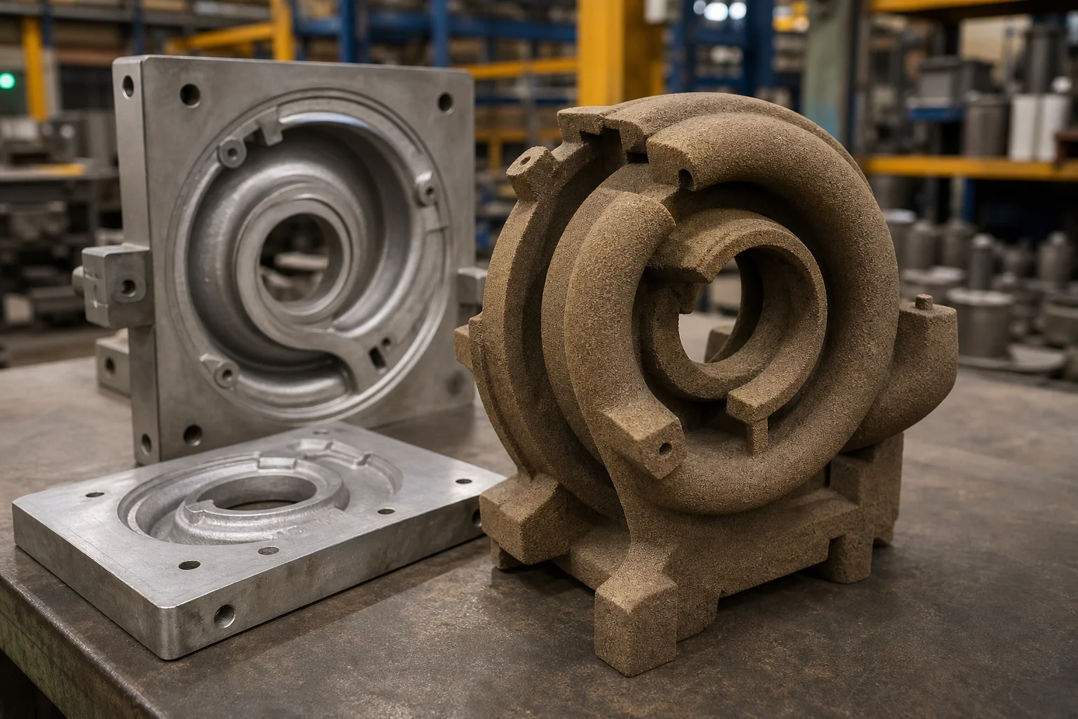
The internal volute core is the single most critical tooling element. Foundries utilize chemically bonded resin sand (cold box amine gas or hot box) shot into precision-machined aluminum or hardened steel core boxes:
Turbine housings have drastic section transitions: the heavy inlet mounting flange (15–25 mm thick) sits directly adjacent to thin aerodynamic scroll walls (3.5 mm thick). Without optimized directional solidification, shrinkage cavities will form at the scroll tongue junction.
Molten Alloy Inflow
      │
      ▼
┌──────────────┐     Filtered Bottom Gating
│ Ceramic Foam │ ──► (Minimizes Turbulence & Oxide Inclusions)
│ Filter       │
└──────┬───────┘
       │
       ▼
┌───────────────────────────────────────────────┐
│ Solidification Front Directional Progression   │
│ Thin Volute Wall (Fast Freeze: ~15s)          │
│       │                                       │
│       ▼                                       │
│ Intermediate Body Wall (~45s)                 │
│       │                                       │
│       ▼                                       │
│ Heavy Mounting Flange & Insulated Riser (>120s)│
└───────────────────────────────────────────────┘
Modern foundries utilize casting simulation (MAGMASOFT / ProCAST) to model:
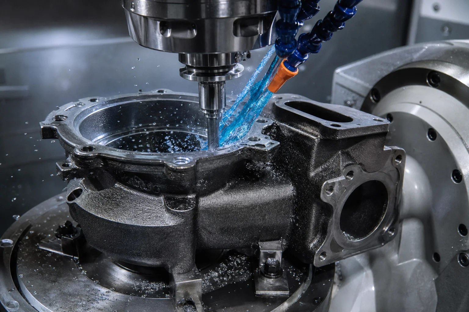
A cast turbine housing is only as good as its finished machining. The component must interface seamlessly with the bearing center housing rotating assembly (CHRA), exhaust manifold, and downpipe.
| Quality Inspection Method | Test Standard / Parameter | Acceptance Criteria |
|---|---|---|
| Chemical Composition | Direct-Reading Optical Emission Spectrometry (OES) | Strict conformance to Ni, Cr, Si, Mo, and trace elements (Pb, Bi, Sb ) |
| Volumetric Soundness | Radiographic Testing (RT) per ASTM E446 / ASTM E192 | Level 1 in critical contour/tongue zones; Level 2 in flange areas |
| Surface Integrity | Fluorescent Penetrant Inspection (FPI / PT) per ASTM E1417 | Zero linear indications on machined contours, seal faces, and wastegate seat |
| Dimensional Verification | 3D Bridge CMM with Scanning Probe (0.001 mm resolution) | 100% feature-to-datum verification against CAD model |
| High-Pressure Leak Test | Dry Air Differential Pressure Decay Testing | Leak rate at 3.5 bar pneumatic pressure |
| Containment / Burst Testing | High-Speed Spin Burst Rig (Over-speed containment) | Housing must fully contain fractured turbine wheel fragments without wall rupture |
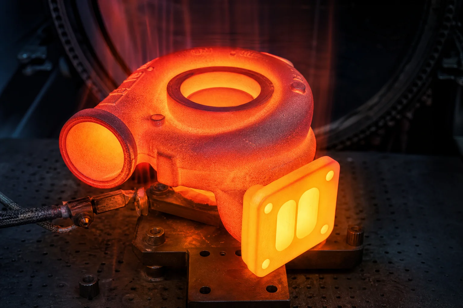
Sourcing high-alloy, precision-machined turbocharger housings requires a manufacturing partner with deep metallurgical mastery and dedicated CNC machining infrastructure.
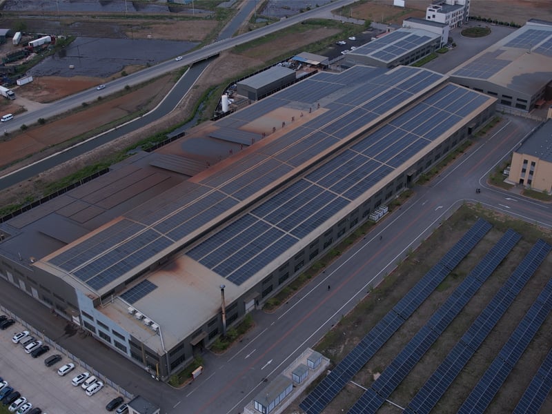
Dandong City Pengxin Machinery Co., Ltd. combines over six decades of advanced ferrous and high-alloy casting expertise with precision multi-axis CNC machining capabilities:
- Material Range: Certified casting of SiMo ductile irons, D-5S austenitic Ni-Resist, and cast heat-resistant stainless steels (1.4837, 1.4848).
- In-House Tooling & Shell Coring: Automated core shooting lines capable of producing ultra-smooth, dimensionally stable volute cores for single, twin-scroll, and variable-geometry turbine housings.
- Multi-Axis CNC Finishing: Dedicated CNC turning-milling centers delivering precision contouring, tight bearing bore tolerances, and flat sealing faces.
- Traceability & Documentation: EN 10204 3.1 material certificates, spectrometer chemical analysis, CMM dimensional inspection reports, and pressure decay test validation with every shipment.
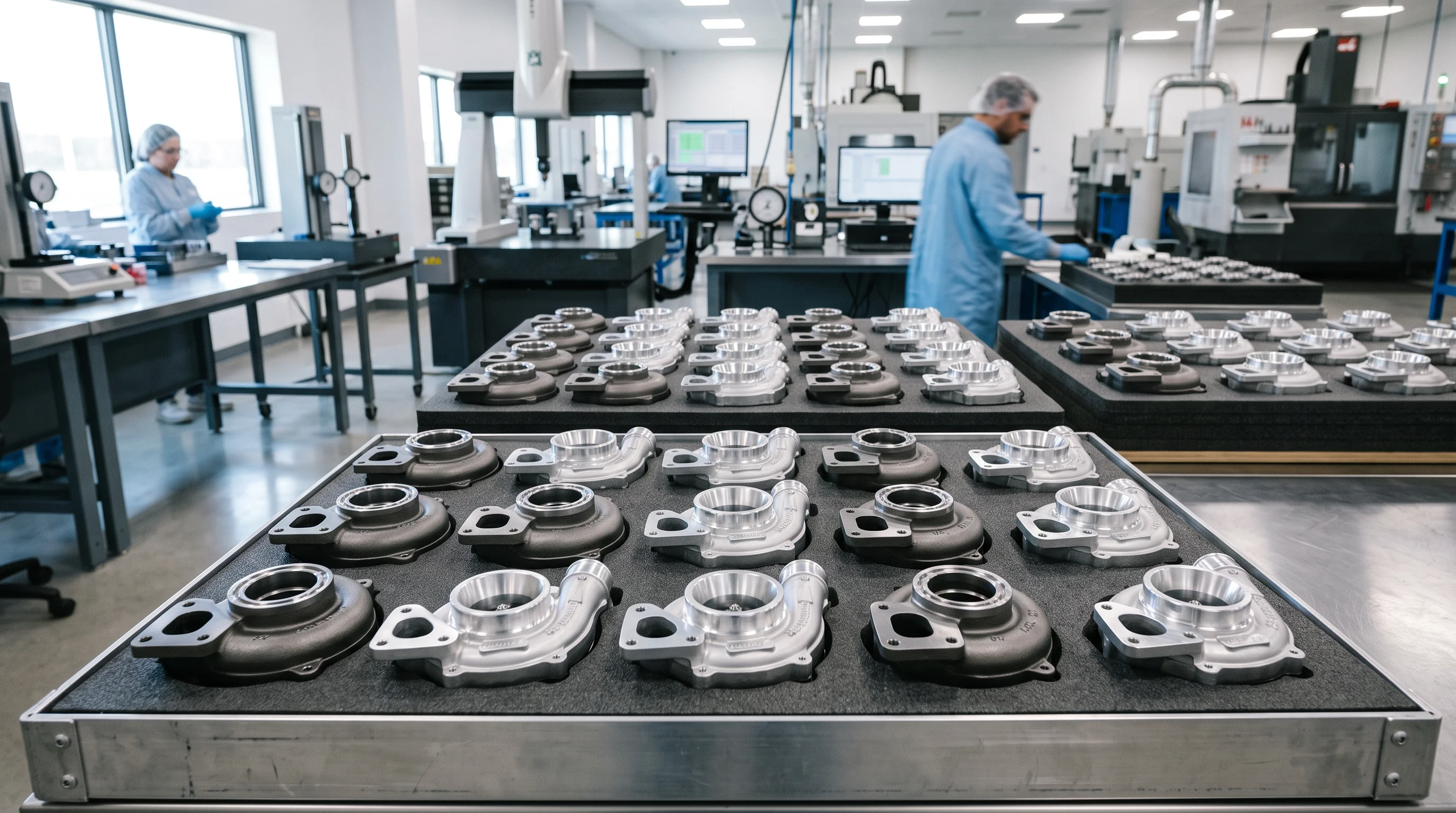
Turbocharger turbine and compressor housings represent the pinnacle of high-temperature casting and precision machining. Balancing the demands of extreme thermal cycling, oxidation resistance, aerodynamic contouring, and sub-hundredth-millimeter machining tolerances requires unyielding process discipline at every stage — from scrap alloy purification to final CMM inspection.
Whether developing next-generation commercial vehicle turbochargers or specialized aftermarket performance components, engineering success begins with an integrated foundry and machining partner.
Contact Dandong City Pengxin Machinery Co., Ltd. today to review your turbocharger housing drawings and technical specifications.
Dandong City Pengxin Machinery Co., Ltd. — Heavy Castings and Precision Machining, Since 1958.
 Hot News
2026-10-16
2026-10-09
2026-10-02
2026-09-25
2026-09-18
2026-09-11

Dandong City Pengxin Machinery was founded in 1958, is a set of casting, machining and assembly as one of the private enterprises.
Wangjiapu Group, Xinan Village, Qianyang Town, Donggang City, Dandong City, Liaoning Province, China
Copyright © Dandong City Pengxin Machinery Co.,Ltd. All Rights Reserved Privacy Policy Blog
 EN
EN