Meta Description: A comprehensive engineering guide to Design for Manufacturability (DFM) in metal casting and CNC machining. Learn how wall thickness, draft angles, fillets, machining allowance, and datum strategy affect casting yield, machining cost, and final part quality.
A casting drawing that looks perfect on screen can be impossible to produce on the foundry floor. The gap between CAD idealization and manufacturing reality is where cost overruns, delivery delays, and quality failures originate — and it is almost always traceable to design decisions made before the first pattern was cut.
Design for Manufacturability (DFM) in metal casting is the disciplined practice of designing a part so that it can be cast successfully, machined efficiently, and delivered at the target cost and quality. It is not about compromising engineering intent — it is about achieving that intent through a design language the manufacturing process understands.

This guide covers the DFM principles that govern sand casting, investment casting, and shell mold casting, with specific attention to how casting design decisions propagate into machining operations. Whether you are designing a new valve body, a pump housing, an exhaust manifold, or a heavy structural casting, these principles apply.
Uniform wall thickness is the golden rule of casting design — and the one most frequently violated in practice. Non-uniform sections create differential cooling rates, which produce thermal stresses, distortion, hot tears, and shrinkage porosity.
| Casting Process | Minimum Wall Thickness (Steel) | Minimum Wall Thickness (Iron) | Minimum Wall Thickness (Stainless) |
|---|---|---|---|
| Sand casting | 5–6 mm (small parts); 8–10 mm (large) | 4–5 mm | 6–8 mm |
| Shell mold casting | 3–4 mm | 3–4 mm | 4–5 mm |
| Investment casting | 1.5–2.0 mm | 1.5–2.0 mm | 1.5–2.5 mm |
These are practical minima — not recommended design targets. Adding 1–2 mm above the minimum significantly improves casting yield (the percentage of poured metal that becomes saleable castings) and reduces rejection rates.
When section changes are unavoidable, follow these rules to minimize stress concentration and solidification defects:
| Transition Type | Maximum Ratio | Recommended Geometry |
|---|---|---|
| Step change (abrupt) | 2:1 | Avoid entirely if possible |
| Tapered transition | 3:1 | Linear taper over a length ≥ 3× the thickness difference |
| Radiused transition | 3:1 | Blend with a radius ≥ the smaller thickness |
Practical example: A valve body with a 10 mm body wall transitioning to a 25 mm flange. A step change from 10 mm to 25 mm will create a shrinkage cavity at the junction center — a defect that machining will expose but not eliminate. The correct design uses a tapered transition over at least 45 mm with generous internal and external fillet radii.
Machining consequence: Shrinkage porosity at section transitions is the most common cause of casting rejection discovered during machining. The machinist cuts into what appears to be sound metal only to expose internal voids. These cannot be weld-repaired reliably and typically result in scrapped castings. The foundry's cost for a scrapped machined casting includes both the casting cost and the wasted machining hours.
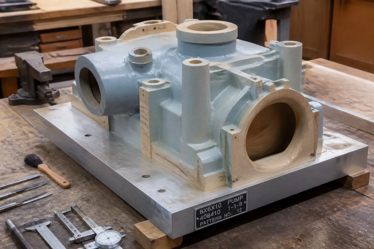
Draft is the taper applied to surfaces parallel to the mold parting direction, enabling the pattern to be withdrawn without damaging the mold cavity.
| Surface Type | Minimum Draft (Sand Casting) | Recommended Draft | Notes |
|---|---|---|---|
| External surfaces | 1° | 2–3° | Deeper cavities need more draft |
| Internal surfaces (cores) | 1.5° | 3–5° | Core surfaces shrink onto the core — higher draft essential |
| Deep pockets (depth > 3× width) | 3° | 5–7° | Increased draft compensates for mold wall friction |
| Investment casting | 0° | 0.5–1° | Pattern is melted out; draft is not technically required but aids shell building |
Draft direction convention: Draft is always applied as added material — the as-cast surface at the parting line defines the nominal dimension, and material is added as the surface recedes from the parting line. This means draft increases casting weight slightly and creates a surface that is not perpendicular to the parting plane — both of which affect the machining strategy.
Machining consequence: Drafted surfaces that are functional (sealing faces, bearing seats, locating features) must be machined to square. The designer must ensure sufficient machining allowance at the small end of the draft (where the cast surface is farthest from the finished surface). A common DFM error is specifying 3 mm machining allowance at the parting line but only achieving 0.5 mm at the draft's far end — insufficient for clean-up.
Sharp internal corners are the enemy of castings. They act as stress concentrators, hot-spot nucleation sites for shrinkage, and crack initiation points during cooling. Every internal corner must have a radius.
| Location | Minimum Radius | Recommended Radius |
|---|---|---|
| Internal corners | R ≥ 0.25 × adjacent wall thickness | R ≥ 0.5 × wall thickness |
| External corners | R ≥ 0.125 × wall thickness | R ≥ 0.25 × wall thickness |
| Boss-to-wall junctions | R ≥ 0.5 × boss diameter | R ≥ boss diameter for heavy bosses |
| Flange-to-body transitions | R ≥ flange thickness | R ≥ 1.5 × flange thickness for cyclic loading |
The parting line corner trap: Internal corners that coincide with the mold parting line are particularly vulnerable. The parting line is a plane of weakness in the mold, and sharp corners at this location are prone to sand erosion during pouring — producing sand inclusions in the casting. Always radius parting line intersections generously.
Machining consequence: Internal fillets that are too small force the machinist to use smaller-diameter cutting tools to reach into corners, reducing tool rigidity and increasing cycle time. A fillet radius of R6 mm instead of R3 mm may allow the machinist to use a 10 mm end mill instead of a 5 mm end mill — approximately doubling metal removal rate and tool life.
Bosses and pads are added to castings to provide material for machined features — threaded holes, bearing seats, gasket faces. Their design directly affects casting soundness and machining cost.
| Rule | Specification | Rationale |
|---|---|---|
| Boss height | ≤ 2× boss diameter for isolated bosses | Taller bosses create hot spots that draw shrinkage |
| Boss spacing | Center distance ≥ 2× boss diameter | Closer spacing merges solidification fronts, creating a combined hot spot |
| Boss connection | Connect to nearest wall with a web or gusset | Isolated bosses cool last — guaranteed shrinkage unless fed by a riser |
| Machining pad height | 3–5 mm above adjacent as-cast surface | Minimizes metal removal on non-functional surfaces; reduces machining time |
A common design error is specifying a large flat machining pad that covers an entire face of the casting — for example, a 150 mm × 150 mm pad when only a 50 mm diameter gasket surface needs to be machined. The oversized pad:
Correct approach: Design the pad to cover only the machined area plus a small margin (5–10 mm). The rest of the face can remain as-cast, saving weight, reducing shrinkage risk, and focusing machining effort where it is needed.
DFM is not only about part geometry — it is also about how the part interacts with the casting process infrastructure: where metal enters, how it solidifies, and where the mold splits.
The parting line is the plane where the two mold halves meet. The designer should indicate the intended parting line on the casting drawing or, at minimum, understand the implications of its placement.
| Parting Line Consideration | Design Impact |
|---|---|
| Parting line through machined surfaces | Preferred — parting line flash is removed during machining |
| Parting line through as-cast surfaces | Requires grinding/fettling; may leave visible witness line |
| Parting line through critical features | Avoid — flash, mismatch, and draft all concentrate at the parting line |
| Multi-parting (irregular parting) | Increases pattern cost and molding complexity; use only when necessary |
Design rule: Orient the part so that the majority of machined surfaces lie at or near the parting plane. This minimizes the draft effect on critical surfaces and places the parting line flash where it will be removed by machining.
Risers (feeders) are reservoirs of molten metal that compensate for solidification shrinkage. They must be attached to the heaviest sections of the casting — the last areas to freeze. After solidification, risers are cut off, leaving a residual stub that must be machined or ground flush.
| Riser Contact Design | Recommendation |
|---|---|
 |
| Riser on machined surface | Add 5–8 mm extra allowance at the riser contact point to ensure clean-up | | Riser on as-cast surface | Design a recessed pad (breaker core) so the riser breaks cleanly below the casting surface | | Multiple risers | Group riser contacts on the same face where possible to consolidate machining set-ups |
Machining consequence: Riser stubs are typically harder than the surrounding casting (faster cooling, finer grain structure). The first machining pass at a riser contact point requires reduced feed rate to avoid tool damage. Designers who specify the riser contact location on a non-critical surface eliminate this machining difficulty entirely.
The gating system (sprue, runners, ingates) is attached to the casting at ingate locations. Like risers, these must be removed after casting.
DFM rule: Position ingates on surfaces that will be machined. Ingate stubs on as-cast functional surfaces require grinding and may leave surface defects that compromise fatigue life or sealing performance.
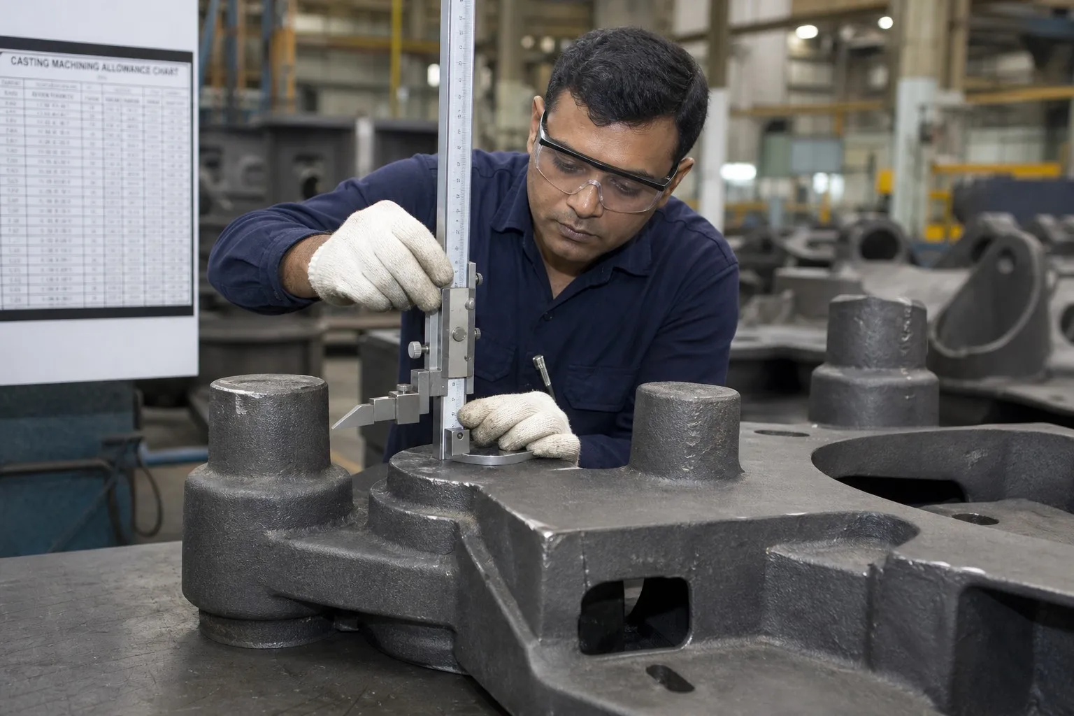
Machining allowance is the extra material added to as-cast surfaces to ensure that machining can achieve the finished dimensions. Too little allowance risks incomplete clean-up (casting skin remains on the machined surface); too much wastes material and machining time.
| Casting Size (max dimension) | Sand Casting (Steel/Iron) | Investment Casting (Steel) | Shell Mold (Iron) |
|---|---|---|---|
| ≤ 250 mm | 2.0–3.0 mm | 0.5–1.0 mm | 1.5–2.0 mm |
| 250–500 mm | 3.0–5.0 mm | 1.0–1.5 mm (rare at this size) | 2.0–3.0 mm |
| 500–1,000 mm | 5.0–8.0 mm | N/A | 3.0–5.0 mm |
| 1,000–2,000 mm | 8.0–12.0 mm | N/A | N/A |
| > 2,000 mm | 12.0–20.0 mm | N/A | N/A |
These are general guidelines. The required allowance depends on:
For precision components, specify allowance in two stages:
This approach is standard in automotive (IATF 16949) and aerospace (AS9100) supply chains. It adds one machining operation but dramatically improves first-pass yield by exposing casting defects at the roughing stage, before finish machining time is invested.
The single most consequential DFM decision that affects both casting and machining is the selection of the machining datum reference frame. The datum strategy determines how the raw casting is located and clamped for the first machining operation — and it must work with a casting that has inherent dimensional variation.
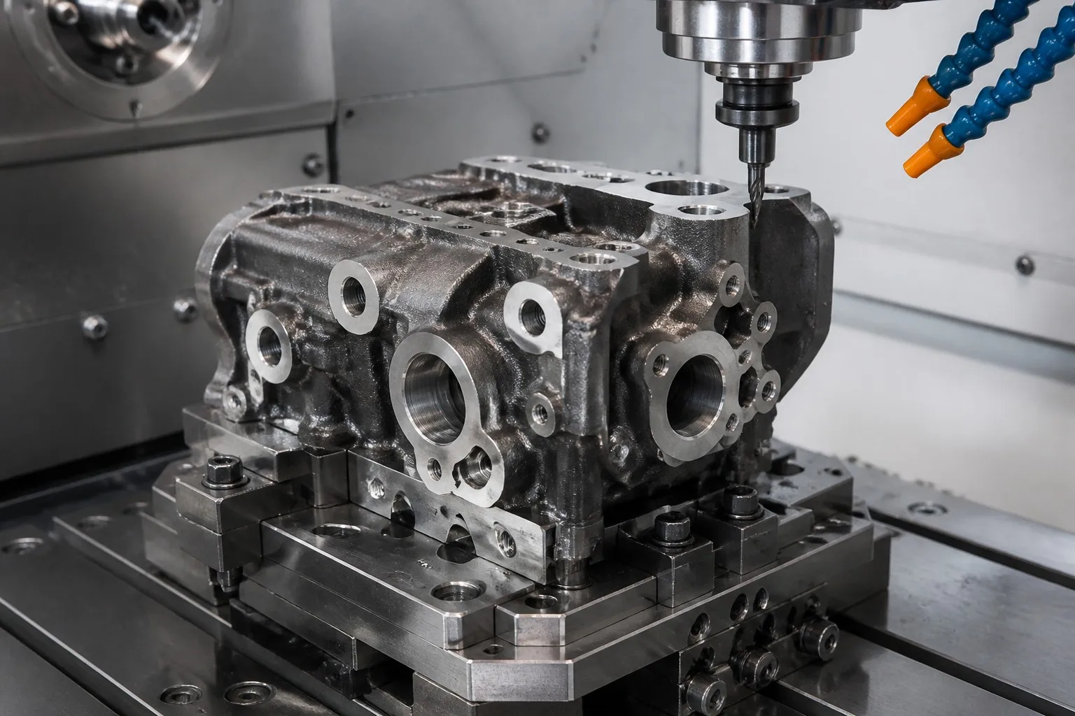
The 3-2-1 principle is the foundation of casting fixture design:
| Datum | Contact Points | Function |
|---|---|---|
| Primary datum (A) | 3 points (defines a plane) | Locates the casting in the Z axis; establishes the first machined face |
| Secondary datum (B) | 2 points (defines a line) | Locates in Y and constrains rotation about Z |
| Tertiary datum (C) | 1 point (defines a point) | Locates in X and constrains rotation about Y and Z |
| Rule | Explanation |
|---|---|
| Use as-cast surfaces as locating points | The first operation must locate from as-cast surfaces — not from previously machined features. Design the casting with three small raised pads (locating pads) specifically for this purpose. |
| Locating pads should be on one mold half | Cross-parting-line surfaces introduce mismatch error (typically 0.5–1.5 mm for sand castings). All three locating pads should be on surfaces formed by the same mold half. |
| Avoid locating from gating/riser contact areas | These surfaces have the highest dimensional variability due to riser removal and localized shrinkage. |
| Design locating pads with draft in the correct direction | Draft on locating pads must not reduce the contact area. A 10 mm × 10 mm pad with 3° draft on all sides leaves a contact area of approximately 7 mm × 7 mm — plan for this. |
The first machining operation — called the qualifying cut or spot-facing — machines the three locating pads to create a clean, flat, orthogonal reference frame. All subsequent machining operations reference these qualified surfaces.
DFM requirement: The casting drawing must explicitly identify the three locating pads with a note such as: "Locating pads A, B, and C to be spot-faced to establish datum reference frame prior to all other machining operations."
| Error | Consequence |
|---|---|
| Datum on a drafted surface | The locating point moves up the draft face as casting variation changes the contact height; positional error is amplified by the draft angle |
| Datum on the parting line | Parting line mismatch creates a step at the datum surface; the fixture contacts an inconsistent surface |
| Insufficient locating pad area | Clamping force deforms the as-cast surface; the casting shifts during machining |
| Datum on a thin wall | Clamping deflects the wall; when the clamp is released after machining, the wall springs back and the machined feature is out of position |
| Feature | Casting Limitation | Design Recommendation |
|---|---|---|
| Through holes | Cannot be cast to size in sand casting below ~20 mm diameter | Design as solid; machine to finished size. For mass production, consider casting a cored hole at ~60–70% of finished diameter to reduce drilling time |
| Blind holes | Cannot be cast in sand casting (core cannot be supported) | Always machined |
| Threaded holes | Cannot be cast with functional threads | Cast a solid boss; drill and tap after casting |
| Deep bores (L/D > 5) | Casting core may shift or break | Use a stepped bore — larger diameter at entry, reducing to finished size — to guide the drill and reduce tool deflection |
| Requirement | Design Recommendation |
|---|---|
| Flatness < 0.05 mm | Surface grinding after milling; specify additional 0.2–0.3 mm finish grinding allowance |
| Flatness 0.05–0.10 mm | Finish face milling; adequate with sharp tooling and rigid fixturing |
| Large faces (> 300 mm) | Multiple clamping points to prevent workpiece deflection; consider stress-relief anneal before finish machining |
Internal undercuts (re-entrant features, internal grooves, intersecting bores) are the most expensive features to produce in a casting. They require complex, collapsible, or multi-piece cores that increase pattern cost, molding time, and rejection rate.
| Undercut Type | DFM Guidance |
|---|---|
| External undercut | Can be formed by the mold cavity if the parting line is placed appropriately. Often resolved by adding a parting line step or a loose piece. |
| Internal undercut (blind) | Requires a collapsible or soluble core — significant cost adder. Redesign to eliminate if possible. |
| Internal undercut (through) | Can be formed by a two-piece core if the core prints allow extraction. Less expensive than blind undercuts but still adds complexity. |
Redesign strategies for undercuts:
One of the most common DFM failures is assigning machined tolerances to as-cast features, or vice versa. The achievable tolerance depends entirely on which process produces the feature.
| Feature | As-Cast Tolerance (Sand) | As-Cast Tolerance (Investment) | Machined Tolerance (CNC) |
|---|---|---|---|
| Linear dimension ≤ 100 mm | ±1.0 mm | ±0.3 mm | ±0.05 mm |
| Linear dimension 100–500 mm | ±2.0 mm | ±0.5 mm | ±0.10 mm |
| Linear dimension 500–1,000 mm | ±3.0 mm | N/A | ±0.15 mm |
| Flatness (per 100 mm) | ±1.0 mm | ±0.3 mm | ±0.02 mm |
| Surface roughness (Ra) | 6.3–25 μm | 1.6–6.3 μm | 0.4–3.2 μm |
A properly executed casting drawing distinguishes between:
Critical rule: Never include the machining allowance in the finished part dimensions on the drawing. The finished dimension is the target. The casting drawing adds allowance; the machining drawing removes it. Mixing these conventions is the most common source of drawing interpretation errors between designers and foundries.
Effective DFM is not a checklist applied after the design is complete — it is an iterative dialogue between the design engineer and the foundry engineer. The earlier this dialogue begins, the more cost and time it saves.
| Design Phase | DFM Activity | Value |
|---|---|---|
| Concept design | Foundry reviews part envelope, material, and general geometry for castability | Avoid fundamentally uncastable concepts |
| Detailed design | Foundry reviews wall thicknesses, draft, fillets, parting line | Optimize geometry for casting yield |
| Pre-release | Foundry provides formal DFM report with machining strategy, datum plan, and tolerance capability analysis | Lock in manufacturing plan before tooling investment |
| Pattern/tooling design | Foundry and pattern shop finalize gating, riser, and rigging design | Ensure pattern produces castings that machine correctly |
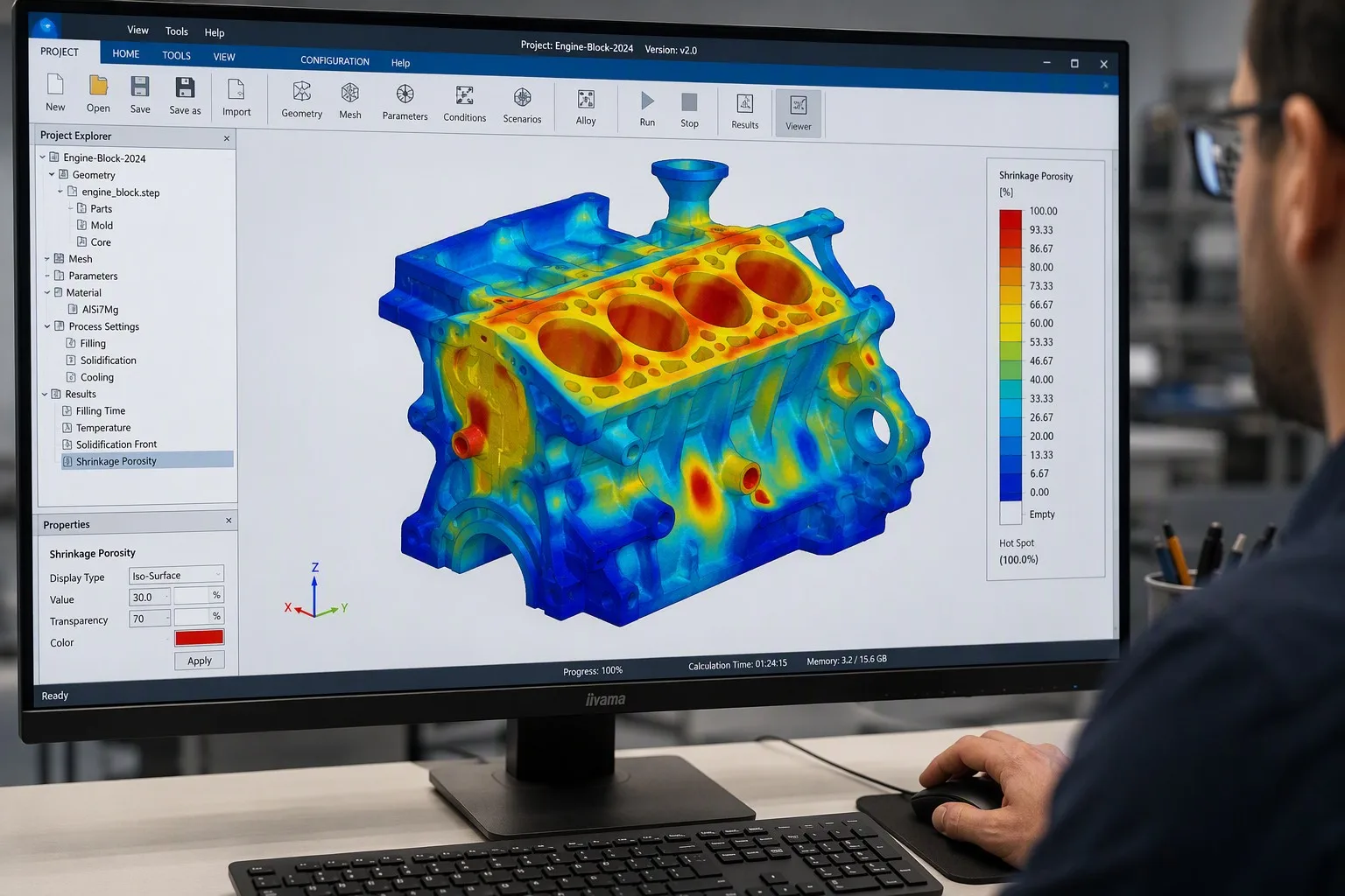
A professional foundry DFM report should include:
If a foundry accepts a casting drawing without questions, without a DFM report, and without recommended modifications, be cautious. Every casting design has optimization opportunities — a foundry that finds none is either not reviewing the design carefully or not communicating honestly.
To make DFM principles tangible, here is the approximate cost impact of common design decisions on a medium-complexity steel casting (5–50 kg finished weight):
| Design Decision | Cost Impact | Direction |
|---|---|---|
| Optimize wall thickness uniformity | -15% to -25% casting cost | Reduces rejection rate, improves yield |
| Add draft angles (vs. none) | +2% to +5% pattern cost; -10% to -20% molding cost | More than offsets through reduced mold damage and faster molding |
| Increase internal fillet radii from R3 to R6 | +5% pattern cost; -10% to -15% rejection rate | Prevents hot tears and shrinkage at junctions |
| Eliminate an internal undercut (redesign) | -30% to -50% core cost | Often eliminates a complex multi-piece core |
| Move parting line onto machined surface | -5% to -10% fettling cost | Parting line flash removed by machining, not grinding |
| Add 2 mm extra machining allowance on critical surface | +3% to +5% machining time | Prevents scrap from incomplete clean-up; pays back in first-article yield |
| Specify locating pads on casting drawing | +2% pattern cost; -10% to -15% fixture cost | Standardized locating reduces custom fixture complexity |
| Engage foundry at concept phase vs. after design release | -20% to -40% total project cost | Avoids redesign loops and tooling modifications |
Design for Manufacturability in metal casting is not a constraint on engineering creativity — it is the discipline that converts creative designs into producible, profitable parts. Every hour spent on DFM before tooling is ordered saves days of troubleshooting after the first castings arrive.
The four pillars of casting DFM:
The foundry that asks questions about your design, proposes modifications, and delivers a detailed DFM report is not being difficult — it is being professional. The alternative is a casting that looks right in the CAD model but costs twice as much and takes three times as long to qualify.
Planning a new casting project? Our engineering team provides comprehensive DFM analysis — from casting feasibility assessment and gating simulation to machining datum strategy and full PPAP documentation. Contact us to schedule a design review before your next tooling investment.
 Hot News
2026-10-16
2026-10-09
2026-10-02
2026-09-25
2026-09-18
2026-09-11

Dandong City Pengxin Machinery was founded in 1958, is a set of casting, machining and assembly as one of the private enterprises.
Wangjiapu Group, Xinan Village, Qianyang Town, Donggang City, Dandong City, Liaoning Province, China
Copyright © Dandong City Pengxin Machinery Co.,Ltd. All Rights Reserved Privacy Policy Blog
 EN
EN