Meta Description: A comprehensive guide to Non-Destructive Testing (NDT) methods for steel and iron castings. Learn MT, UT, RT, PT, VT, pressure testing, and chemical/mechanical analysis — with ASTM/EN standards, acceptance criteria, and how to specify inspection requirements correctly.
Casting quality cannot be inspected into a part after it is produced — but it can be verified before the part leaves the foundry. Non-Destructive Testing (NDT) is the engineering discipline that makes this verification possible, enabling foundries and buyers to detect surface and subsurface defects without damaging or destroying the casting.
For procurement managers and engineers sourcing cast components, understanding NDT methods is not optional. The difference between specifying "do NDT" and specifying "MT per ASTM E709, acceptance to ASTM A903 Severity Level II, by an ASNT Level II-certified inspector" is the difference between subjective judgment and verifiable quality.
This guide covers the six principal NDT methods applied to metal castings, their underlying physics, capabilities and limitations, applicable standards, acceptance criteria, inspector qualification requirements, and how to specify NDT requirements correctly on drawings and purchase orders.
Before selecting specific NDT methods, determine what you are looking for and why.
| Defect Category | Examples | Typical Detection Methods |
|---|---|---|
| Surface defects | Cracks, hot tears, cold shuts, surface porosity, sand inclusions, gas holes | VT, MT (ferromagnetic), PT (all metals) |
| Subsurface defects | Subsurface porosity, inclusions, shrinkage within 3–6 mm of surface | MT (shallow subsurface), UT |
| Internal defects | Deep shrinkage cavities, gas porosity, slag inclusions, core shift | UT, RT |
| Dimensional non-conformance | Wall thickness deviation, core shift, warpage | CMM, manual layout, UT (thickness gauging) |
| Material non-conformance | Wrong alloy grade, incorrect heat treatment, decarburization | Spectrometer, hardness testing, metallography |
| Method | Detects | Surface / Subsurface / Internal | Ferromagnetic Only? | Relative Cost | Speed |
|---|---|---|---|---|---|
| VT (Visual) | Surface cracks, porosity, sand, misruns, surface finish | Surface only | No | Very low | Fast |
| MT (Magnetic Particle) | Surface and near-surface cracks, seams, laps | Surface + shallow subsurface (≤3 mm) | Yes (steel, iron) | Low | Fast |
| PT (Dye Penetrant) | Surface-breaking cracks, porosity | Surface only | No (all metals) | Low | Moderate |
| UT (Ultrasonic) | Internal porosity, shrinkage, inclusions, laminations, thickness | Subsurface + internal | No | Moderate | Moderate |
| RT (Radiographic) | Internal porosity, shrinkage, inclusions, cracks (orientation-dependent) | Internal (volumetric) | No | High | Slow |
| Leak / Pressure Test | Through-wall leaks, casting porosity that creates leak paths | Through-wall only | No | Moderate | Moderate |
| Spectrometer (OES) | Chemical composition | Bulk material | No | Low (per test) | Fast |
| Hardness Test | Mechanical property verification | Surface + subsurface | No | Low | Fast |
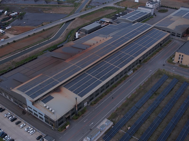
At Dandong City Pengxin Machinery Co., Ltd., in-house NDT capability — including MT, UT, PT, spectrometer analysis, hardness testing, and hydrostatic pressure testing — enables comprehensive quality verification before any casting leaves the facility, with documented inspection reports provided as standard deliverables.
Visual testing is the most basic but arguably most important NDT method. An experienced inspector can identify a wide range of surface defects — cracks, porosity, sand inclusions, cold shuts, misruns, and surface roughness issues — using the naked eye or simple magnification aids.
| Requirement | Specification |
|---|---|
| Lighting | Minimum 1,000 lux at the inspection surface (ASME Section V) |
| Viewing distance | Maximum 600 mm from eye to surface |
| Viewing angle | Not less than 30° from the surface plane |
| Magnification | 2× to 10× for detailed examination of suspect areas |
| Surface condition | Free of paint, scale, dirt, oil, or other contaminants that could mask defects |
Visual acceptance criteria are typically defined by reference standards or customer-specific specifications. Common rejection criteria include:
Only surface-breaking or surface-visible defects are detectable. Subsurface porosity, internal shrinkage, and inclusions pass visual inspection undetected. VT must be supplemented with volumetric NDT for critical applications.
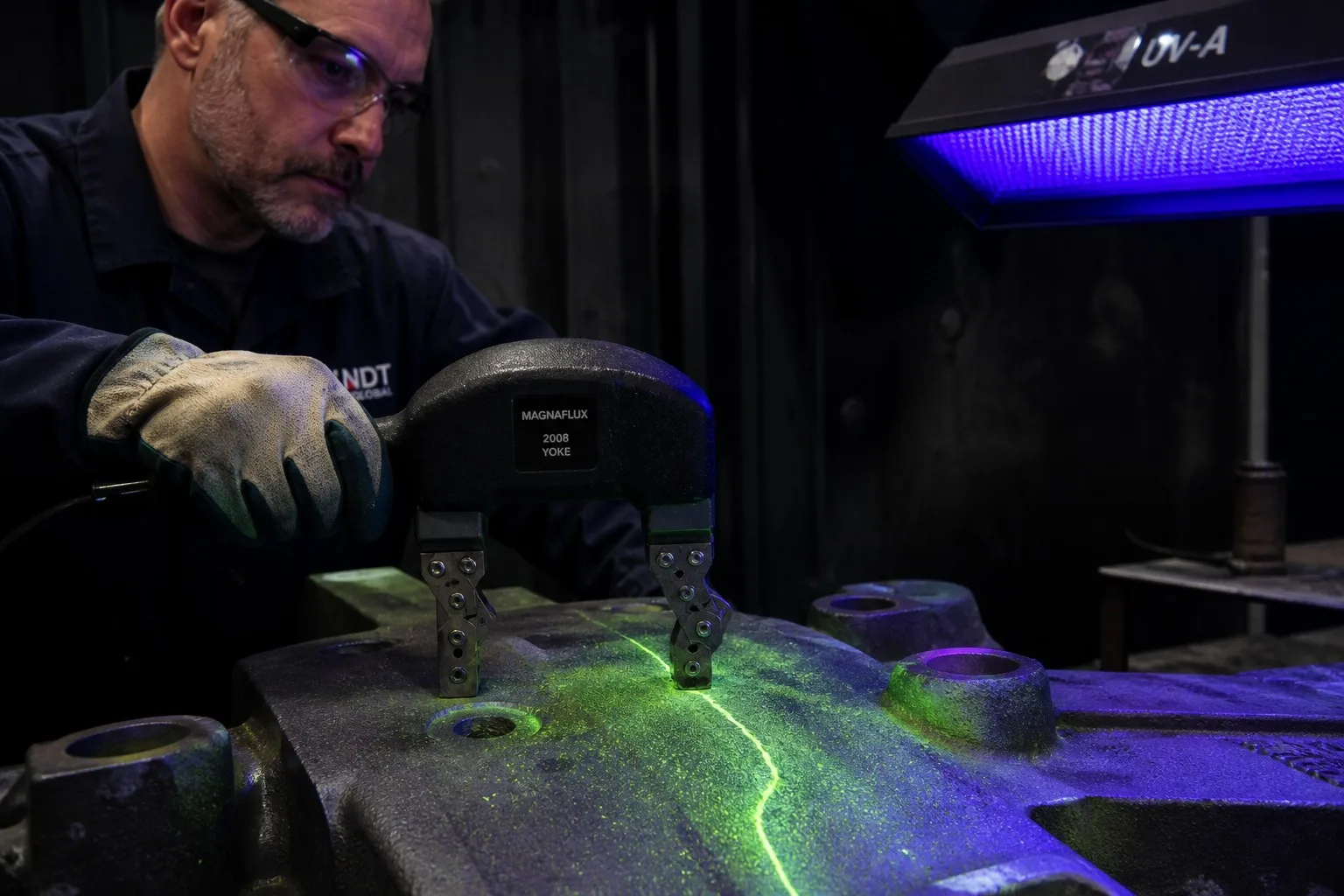
Magnetic particle testing detects surface and near-surface discontinuities in ferromagnetic materials (all steels and irons). It is the most widely used NDT method in steel foundries because it is fast, sensitive, and cost-effective.
A magnetic field is induced in the casting. Surface or near-surface discontinuities distort the magnetic field, creating flux leakage at the defect location. Fine magnetic particles (dry powder or wet fluorescent suspension) applied to the surface are attracted to these leakage fields, forming a visible indication of the defect.
| Magnetization Method | Best For | Equipment |
|---|---|---|
| Yoke (portable electromagnet) | Local inspection; field inspection; large castings | Portable AC or DC yoke |
| Prod (current flow) | Local inspection of thick sections | Prods with contact tips |
| Headshot (direct contact) | Small-to-medium castings; longitudinal defects | Stationary bench unit |
| Central conductor | Cylindrical parts; detects longitudinal defects | Bench unit with conductor bar |
| Coil (indirect) | Detects transverse defects | Encircling coil or cable wrap |
| Defect Type | Minimum Detectable Size | Conditions |
|---|---|---|
| Surface crack | 0.5 mm length, 0.01 mm width | Surface must be clean; discontinuity must be perpendicular to magnetic field |
| Subsurface crack | 1.5 mm length at ≤2 mm depth | Sensitivity decreases rapidly with depth |
| Subsurface porosity | ≥3 mm diameter at ≤3 mm depth | Limited sensitivity for spherical discontinuities |
| Standard | Scope |
|---|---|
| ASTM E709 | Standard guide for magnetic particle testing |
| ASTM A903 / A903M | Acceptance criteria for steel castings |
| ASME Section V, Article 7 | Magnetic particle examination for pressure vessels |
| ISO 4986 | Steel castings — magnetic particle inspection |
| ISO 4987 | Steel castings — liquid penetrant inspection |
| Severity Level | Maximum Indication Size | Typical Application |
|---|---|---|
| Level I | No linear indications; nonlinear indications ≤3 mm | Critical aerospace and nuclear components |
| Level II | Linear ≤3 mm; nonlinear ≤5 mm | Pressure-containing castings, general industrial |
| Level III | Linear ≤6 mm; nonlinear ≤10 mm | Non-critical structural components |
| Level IV | Linear ≤10 mm; nonlinear ≤15 mm | Low-stress, non-safety-critical parts |
| Level V | Larger indications accepted by agreement | Rough service; cosmetic defects only |
Dye penetrant testing detects surface-breaking defects on any non-porous material — ferromagnetic or non-ferromagnetic. It is the primary surface NDT method for austenitic stainless steel, aluminum, and other non-magnetic alloys where MT cannot be applied.
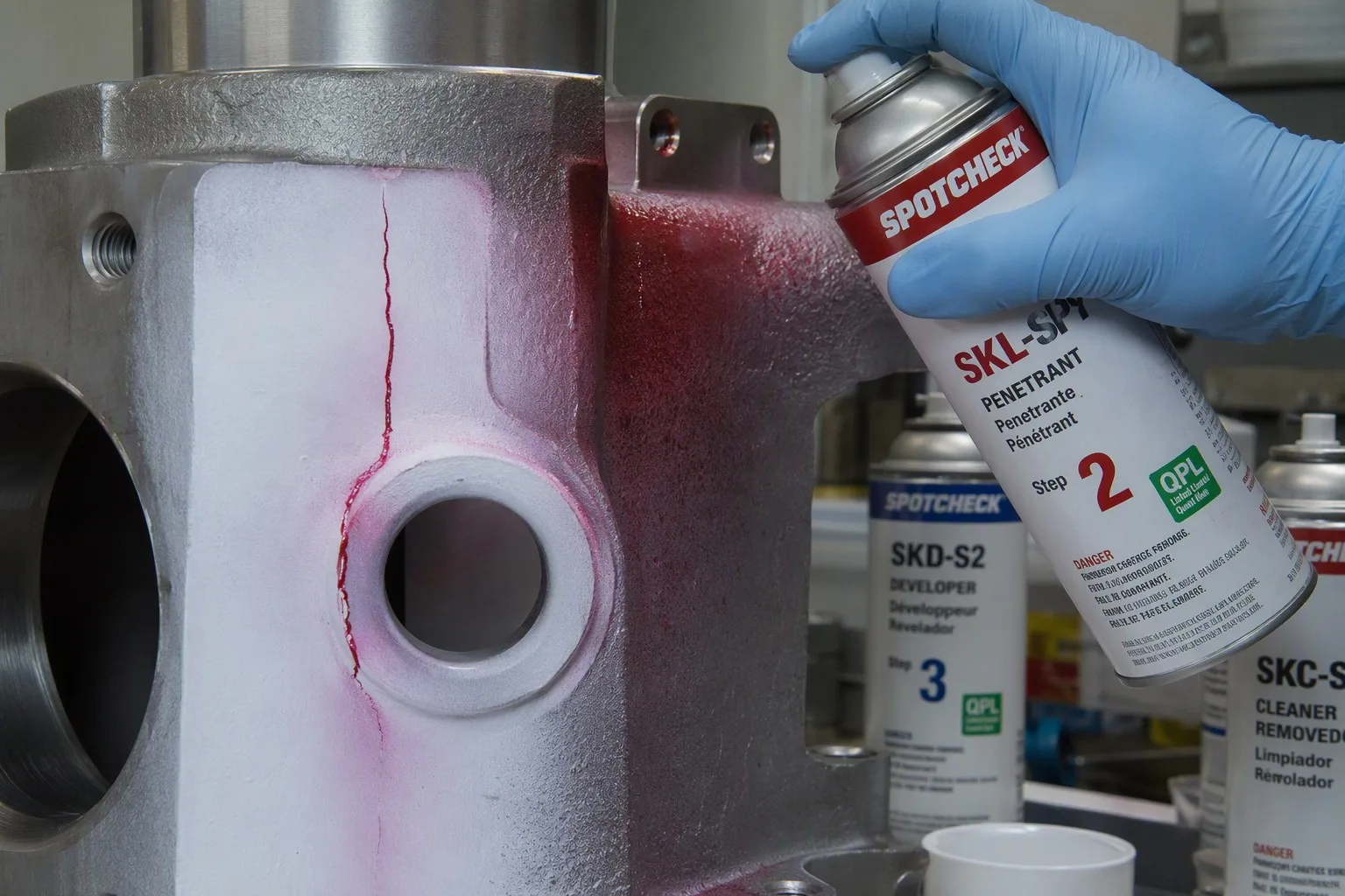
A low-viscosity liquid penetrant is applied to the surface. Capillary action draws the penetrant into surface-breaking discontinuities. After a dwell time, excess penetrant is removed from the surface. A developer is applied, which draws the trapped penetrant back to the surface through blotting action, creating a visible indication.
| Type | Method | Visibility | Sensitivity |
|---|---|---|---|
| Type I — Fluorescent | Post-emulsifiable or water-washable | UV-A light required | Highest sensitivity |
| Type II — Visible (Red Dye) | Solvent-removable or water-washable | White light | Good sensitivity for most applications |
For casting inspection, the visible red dye / solvent-removable system (Type II, Method C) is most common due to its portability and no requirement for UV-A equipment.
| Step | Action | Key Parameters |
|---|---|---|
| 1. Pre-clean | Remove surface contaminants | Solvent clean; ensure surface is dry |
| 2. Apply penetrant | Spray or brush penetrant onto surface | Cover entire inspection area |
| 3. Dwell time | Allow penetrant to enter defects | 10–30 minutes (longer for tight cracks, cold metal) |
| 4. Remove excess | Wipe with solvent-dampened cloth; do NOT spray solvent directly on surface | Remove surface penetrant without washing penetrant from defects |
| 5. Apply developer | Spray thin, uniform layer of developer | Developer draws penetrant from defects; dwell 10–30 minutes |
| 6. Inspect | Examine under white light ≥1,000 lux | Inspect periodically during developer dwell; indications grow over time |
| 7. Post-clean | Remove developer and penetrant residue | Solvent wipe or water wash |
| Advantages | Limitations |
|---|---|
| Works on any non-porous material | Only surface-breaking defects |
| Simple equipment — can be performed in the field | Surface must be clean and dry |
| High sensitivity for fine cracks | Rough as-cast surfaces produce false background indications |
| Low cost per inspection | Temperature-sensitive — avoid below 5 °C or above 50 °C |
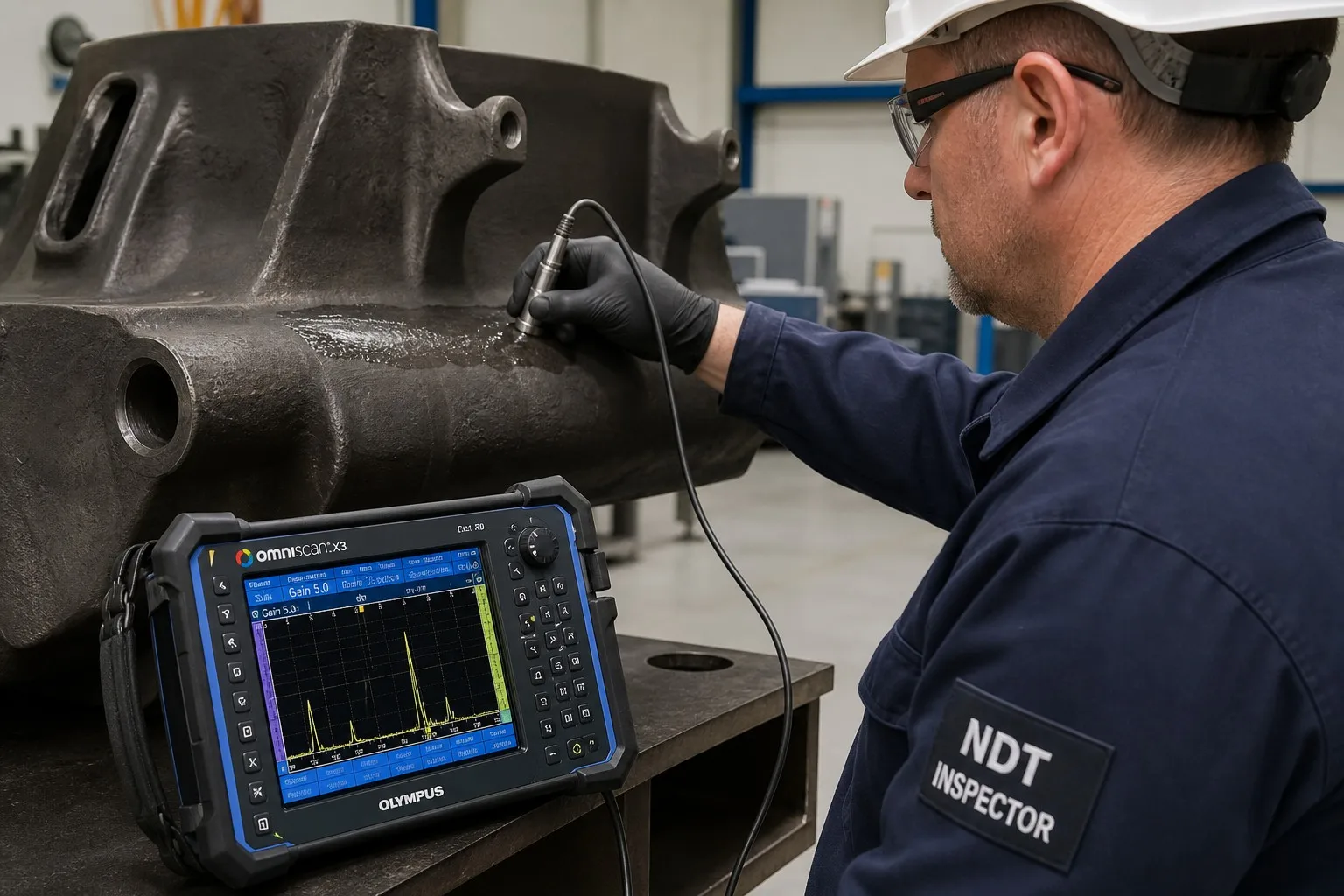
Ultrasonic testing uses high-frequency sound waves (typically 0.5–25 MHz) to detect internal discontinuities and measure material thickness. It is the most versatile volumetric NDT method, applicable to virtually any metal.
A piezoelectric transducer generates ultrasonic pulses that travel through the material. When the sound beam encounters an interface — a discontinuity, the back wall of the casting, or an inclusion — a portion of the energy is reflected back to the transducer. The time delay between pulse transmission and echo reception indicates the distance to the reflector. The echo amplitude indicates the size of the reflector.
| Technique | Application | Advantages |
|---|---|---|
| Straight beam (longitudinal wave) | Thickness measurement; detection of laminar defects parallel to surface; back-wall echo monitoring | Simple; quantitative thickness measurement |
| Angle beam (shear wave) | Detection of cracks and defects oriented at angles to the surface; weld inspection | Detects non-parallel defects |
| Immersion testing | Automated inspection of complex shapes; improved coupling | Eliminates contact coupling issues |
| Phased array (PAUT) | Electronic beam steering; sector scanning; real-time imaging | Faster coverage; better defect characterization; permanent digital record |
Castings present unique challenges for UT compared to wrought products:
| Challenge | Reason | Mitigation |
|---|---|---|
| Coarse grain structure | Large as-cast grains scatter ultrasound (grain noise), reducing signal-to-noise ratio | Use lower frequency (1–2.25 MHz); normalize or Q&T before UT to refine grain size |
| Surface roughness | As-cast surface prevents good transducer coupling | Machine or grind a smooth surface for transducer contact; use immersion technique |
| Complex geometry | Multiple echoes from geometric features complicate interpretation | Reference standards with identical geometry; experienced operator essential |
| Austenitic stainless steel | Large columnar grains in as-cast austenitic stainless steel cause severe attenuation and beam skewing | Use specialized dual-element or low-frequency transducers; RT may be more reliable |
| Standard | Scope |
|---|---|
| ASTM A609 / A609M | Standard practice for UT of carbon and low-alloy steel castings |
| ASTM E428 | Reference blocks for UT calibration |
| ASME Section V, Article 5 | UT examination methods for pressure vessels |
| ISO 11971 | Steel and iron castings — UT of steel castings for general purposes |
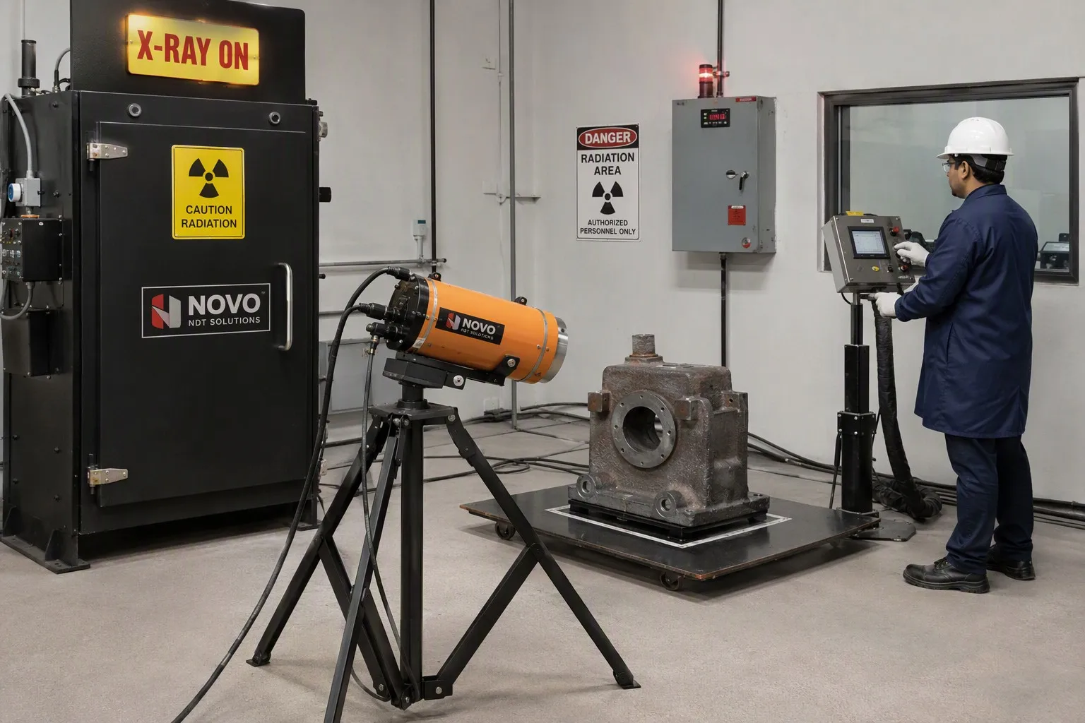
Radiographic testing uses X-rays or gamma rays to produce a shadow image of the internal structure of a casting. It is the most direct method for visualizing internal defects — the radiograph shows their actual shape, size, and location.
Radiation passes through the casting. Areas of reduced thickness or lower density (voids, porosity, shrinkage) absorb less radiation and appear darker on the radiograph. Areas of higher density (inclusions, core material) absorb more radiation and appear lighter.
| Casting Feature | RT Suitability | Notes |
|---|---|---|
| Volumetric defects (porosity, shrinkage, slag) | Excellent | RT is the gold standard for these |
| Planar defects (cracks, lack of fusion, cold shuts) | Orientation-dependent | Crack must be aligned within 5–10° of the radiation beam; cracks perpendicular to the beam are essentially invisible |
| Wall thickness ≤50 mm (steel, X-ray) | Good to excellent | Sensitivity decreases with increasing thickness |
| Wall thickness >50 mm | Requires gamma source (Ir-192, Co-60) or linear accelerator | Longer exposure times; reduced sensitivity |
| Complex geometry | Multiple exposures required | Each section requires a separate exposure at the correct angle |
| Technique | Radiation Source | Energy | Typical Thickness (Steel) |
|---|---|---|---|
| X-ray (conventional) | X-ray tube | 150–450 kV | Up to 50 mm |
| Gamma (Ir-192) | Iridium-192 isotope | ~0.3–0.6 MeV | 10–75 mm |
| Gamma (Co-60) | Cobalt-60 isotope | 1.17, 1.33 MeV | 50–150 mm |
| Linear accelerator (LINAC) | Electron acceleration | 1–15 MeV | 50–500+ mm |
| Digital radiography (DR) | X-ray tube + flat panel detector | Same as X-ray | Same as X-ray; faster, no film processing |
| Computed Tomography (CT) | X-ray + 360° rotation | Same as X-ray | Provides 3D defect mapping; expensive; typically for development/qualification |
Every radiograph must include Image Quality Indicators (IQIs) — thin metal plates with holes or wires of known diameter placed on the casting during exposure. The visibility of the smallest IQI feature on the radiograph confirms the achieved sensitivity.
| IQI Standard | Type |
|---|---|
| ASTM E747 | Wire-type IQI |
| ASTM E1025 | Hole-type IQI |
| ISO 19232 | Wire and step/hole IQIs |
| Standard | Scope |
|---|---|
| ASTM E446 | Reference radiographs for steel castings up to 50 mm |
| ASTM E186 | Reference radiographs for heavy-walled (50–110 mm) steel castings |
| ASTM E280 | Reference radiographs for heavy-walled (110–300 mm) steel castings |
| ASME Section V, Article 2 | Radiographic examination |
| ISO 4992 | Steel castings — RT inspection |
| ISO 5817 | Acceptance levels for imperfections |
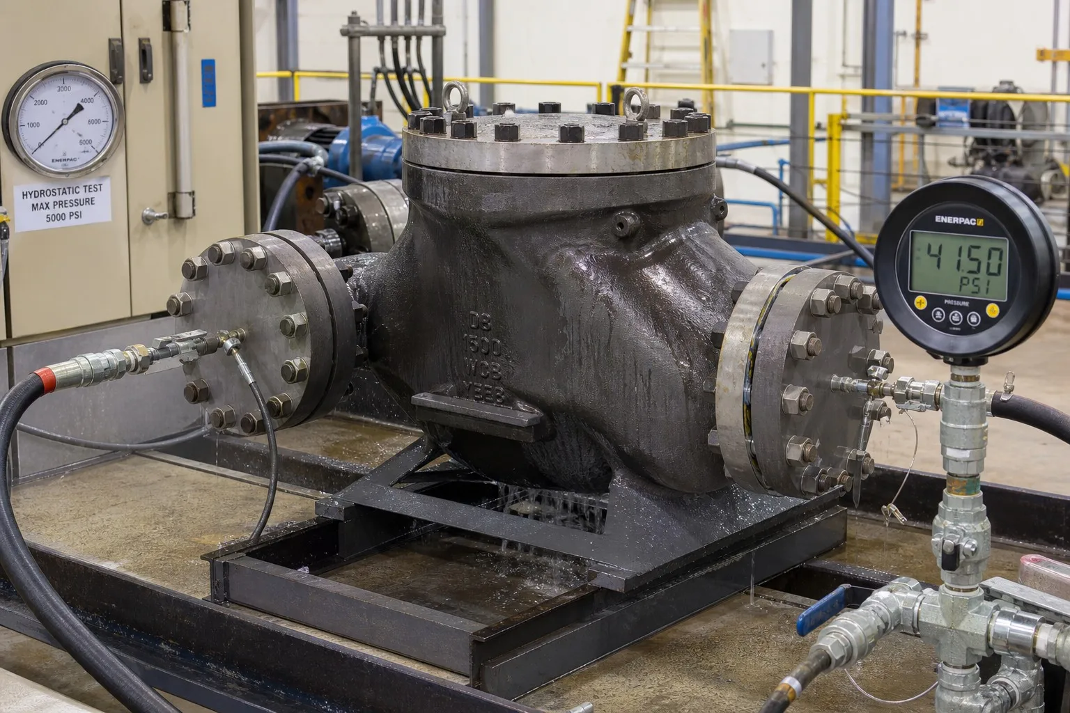
For pressure-containing castings — valve bodies, pump casings, pipe fittings, pressure vessel components — leak testing verifies pressure boundary integrity.
| Parameter | Typical Specification |
|---|---|
| Test pressure | 1.5× design pressure (ASME B16.34 for valves); 1.3× to 1.5× design pressure for pressure vessels |
| Test medium | Water (with corrosion inhibitor and wetting agent); occasionally oil for specific applications |
| Holding time | 15–30 minutes minimum; longer for large castings (>500 kg) |
| Acceptance | No visible leakage, no pressure drop exceeding limits (typically 1–2% maximum) |
| Temperature | Test fluid and casting at approximately ambient temperature; avoid thermal shock |
For applications where water contact is undesirable, pneumatic testing (with air or nitrogen) is used — but with significantly greater safety precautions due to the stored energy of compressed gas:
| Standard | Scope |
|---|---|
| ASME B16.34 | Valve pressure testing |
| API 598 | Valve inspection and testing |
| ISO 5208 | Industrial valves — pressure testing |
| EN 12266 | Industrial valves — testing of metallic valves |
NDT verifies internal soundness and surface condition, but it does not verify that the material itself is correct.
Chemical composition is verified by optical emission spectrometer — an electric arc or spark vaporizes a small amount of the casting surface, and the emitted light spectrum reveals the elemental composition.
| Requirement | Practice |
|---|---|
| Calibration | Daily Type standardization with certified reference materials |
| Sample preparation | Surface ground to remove scale, decarburization, and contamination |
| Analysis | At least two burns per sample; results averaged |
| Reporting | Heat number, analysis date, element percentages, spectrometer identification |
| Test | Equipment | Typical Frequency | Standard |
|---|---|---|---|
| Tensile (UTS, YS, Elongation) | Universal testing machine | One test per heat; test bar cast from same heat | ASTM A370, ISO 6892 |
| Charpy impact | Impact tester with temperature control | Per specification for low-temperature service | ASTM A370, ISO 148 |
| Brinell hardness | Brinell hardness tester (3,000 kg, 10 mm ball for steel) | Every casting or representative sample per lot | ASTM E10, ISO 6506 |
| Rockwell hardness | Rockwell tester | Rapid in-process verification; localized hardness | ASTM E18, ISO 6508 |
For production parts requiring verified dimensional conformance, CMM inspection produces a full 3D point cloud compared to the CAD model. Modern bridge-type or gantry CMMs achieve volumetric accuracy of ±(2.0 + L/300) μm.
For large castings exceeding CMM capacity, manual layout inspection using surface plates, height gauges, vernier calipers, micrometers, and dial indicators remains standard practice.
| Method | Accuracy | Best For |
|---|---|---|
| CMM (bridge type) | ±3–5 μm | Parts up to ~2 m in any axis |
| CMM (gantry type) | ±5–15 μm | Large castings; 2–8 m range |
| Laser tracker | ±25–50 μm over 10 m | Very large castings; slag pots, mill housings |
| Manual layout | ±0.05–0.1 mm (skilled inspector) | One-off and prototype parts; large castings |
NDT results are only as reliable as the inspector producing them. Personnel qualification must be specified as part of the NDT requirement.
| System | Scope |
|---|---|
| ASNT SNT-TC-1A | Employer-based certification; widely used in North America |
| ASNT CP-189 | Central certification standard; alternative to SNT-TC-1A |
| ISO 9712 | International standard for NDT personnel qualification; third-party certification |
| EN 473 (superseded by ISO 9712) | Previously European standard; now harmonized with ISO 9712 |
| Level | Capability |
|---|---|
| Level I | Performs specific NDT operations under Level II or III supervision; cannot interpret results or write procedures |
| Level II | Sets up equipment, performs tests, interprets and evaluates results per approved procedures; writes NDT instructions |
| Level III | Develops NDT procedures and techniques; trains and examines Level I and II personnel; establishes acceptance criteria |
Minimum requirement for independent inspection: All NDT on critical castings should be performed by Level II-certified inspectors working to procedures approved by a Level III.
A complete NDT specification on a casting drawing includes method, standard, extent, acceptance criteria, timing, and personnel qualification:
NON-DESTRUCTIVE TESTING REQUIREMENTS:

MT: 100% of all accessible surfaces per ASTM E709 (continuous yoke method,
fluorescent wet particles). Acceptance to ASTM A903 Severity Level II.
Inspector: ASNT Level II (MT) minimum.

UT: 100% volumetric per ASTM A609. Scan all sections ≥25 mm thickness.
Acceptance: No indication exceeding reference level from 6 mm flat-bottom
hole at the inspection depth. Inspector: ASNT Level II (UT) minimum.

RT: Critical sections as indicated on drawing (Sections A-A, B-B, C-C)
per ASTM E446. Acceptance to Category A, Severity Level 2.
Inspector: ASNT Level II (RT) minimum.

PT: All machined surface-breaking edges and thread roots per ASTM E165
(Type II, Method C). Acceptance: No linear indications. Nonlinear
indications ≤3 mm diameter.

Pressure Test: Hydrostatic at 1.5× design pressure for 30 minutes per
API 598. No visible leakage; pressure drop ≤1% of test pressure.| NDT Activity | When Performed |
|---|---|
| VT of as-cast surface | After shot blasting; before any repair welding |
| MT/PT after weld repair | After PWHT; after final surface preparation |
| UT | After heat treatment (grain refinement improves UT response) |
| RT | After heat treatment; after weld repair |
| Pressure test | After final machining; after all NDE; before painting/coating |
| Final VT | After all operations complete; before packaging |
NDT results must be documented in a form that is traceable to individual castings and auditable by customers and third-party inspectors.
Every NDT report should include:
| Element | Example |
|---|---|
| Part identification | Part number, heat number, casting serial number |
| Inspection method and standard | "MT per ASTM E709" |
| Inspection parameters | Magnetization method, current, particle type, lighting conditions |
| Results | Indication locations, dimensions, types; disposition (accept/reject/repair) |
| Inspector identification | Name, certification level, certification number |
| Date and time | Date of inspection |
| Equipment identification | Equipment type, calibration due date |
| Acceptance criteria reference | Standard and severity level applied |
Companies like Dandong City Pengxin Machinery Co., Ltd. deliver complete inspection documentation packages — including spectrometer reports, mechanical test certificates, MT/UT/PT reports, dimensional inspection data, and pressure test certificates — organized by heat number and traceable to individual castings, meeting the documentation requirements of EN 10204 3.1 and 3.2.
Effective NDT is the difference between shipping castings and shipping qualified castings. A systematic NDT program — one that selects the right methods for the defect types of concern, applies them to the correct extent at the correct point in the manufacturing sequence, interprets results against documented acceptance criteria, and records everything in auditable reports — transforms quality from an aspiration into a verifiable fact.
Key takeaways for specifying NDT:
Require castings with certified NDT and complete inspection documentation? Dandong City Pengxin Machinery Co., Ltd. provides integrated casting, heat treatment, machining, and multi-method NDT inspection from our ISO 9001-certified facility. Contact us with your NDT requirements for a technical quotation.
 Hot News
2026-10-16
2026-10-09
2026-10-02
2026-09-25
2026-09-18
2026-09-11
Dandong City Pengxin Machinery was founded in 1958, is a set of casting, machining and assembly as one of the private enterprises.
Wangjiapu Group, Xinan Village, Qianyang Town, Donggang City, Dandong City, Liaoning Province, China
Copyright © Dandong City Pengxin Machinery Co.,Ltd. All Rights Reserved Privacy Policy Blog
 EN
EN