Meta Description: A comprehensive guide to 20+ metal casting defects — organized by category. Learn to identify surface, internal, dimensional, and material defects, understand their root causes, and implement proven prevention strategies for steel and iron castings.
Every foundry produces defective castings. The difference between a world-class foundry and an average one is not the absence of defects — it is the systematic ability to identify defect root causes, implement corrective actions, and prevent recurrence. For buyers and engineers sourcing cast components, understanding casting defects is essential: it enables informed acceptance decisions, realistic quality expectations, and productive collaboration with foundry technical teams.
This guide categorizes more than 20 casting defects into four groups — surface defects, internal defects, dimensional defects, and material defects — and provides for each: visual identification characteristics, root cause analysis, proven prevention methods, and repair feasibility assessment.
Part 1: Surface Defects
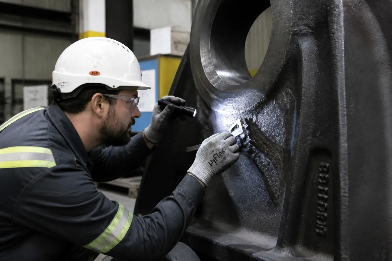
Surface defects are visible on the casting exterior without sectioning or volumetric NDT. They are typically detected by visual inspection (VT), magnetic particle testing (MT), or dye penetrant testing (PT).
1.1 Cracks
Cracks are the most serious category of casting defects — they compromise structural integrity, act as stress concentrators, and can propagate under service loading.
Hot Tears (Hot Cracking)
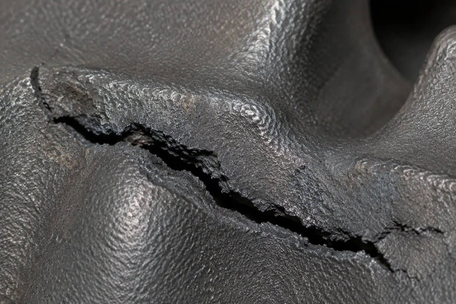
Visual identification: Irregular, jagged, branching cracks with oxidized (dark blue/black) fracture surfaces. Typically occur at section thickness transitions and hot spots. The crack surface shows dendritic morphology, indicating the metal was partially solidified when the fracture occurred.
Root causes:
- Differential cooling rates between thick and thin sections create thermal stresses exceeding the metal's hot strength
- Insufficient mold/core collapsibility — the mold or core resists the casting's natural contraction during cooling
- Poor pattern design with abrupt section transitions and inadequate fillet radii
- Excessive pouring temperature — increases the temperature gradient and thermal stress
- High sulfur or phosphorus content in steel — segregates to grain boundaries and reduces hot ductility
Prevention:
- Design uniform wall thickness; use tapered transitions (≥3:1) between sections of different thickness
- Use collapsible cores and mold materials with good thermal decomposition characteristics
- Add generous fillet radii (≥0.5× wall thickness) at all internal corners
- Control pouring temperature — the minimum temperature that fills the mold completely
- Maintain sulfur below 0.030% and phosphorus below 0.040% for steel castings
- Add chills to accelerate cooling of heavy sections, equalizing cooling rates across the casting
Repair feasibility: Weld-repairable with qualified procedures. Requires complete crack removal by arc gouging or grinding, preheat to 200–350 °C, qualified filler metal, and post-weld heat treatment. Not all applications permit crack repair — check the governing code or specification.
Cold Cracks (Cold Shut Defect)
Visual identification: Narrow, straight cracks with clean (unoxidized), bright fracture surfaces — indicating the crack formed at low temperature after solidification was complete. Often appear at sharp corners, thin sections subjected to residual stress, or areas of high restraint.
Root causes:
- Excessive residual stress from non-uniform cooling — the crack initiates when residual tensile stress exceeds the material's fracture strength at ambient temperature
- Martensite formation in alloy steels quenched too severely — volume expansion during martensitic transformation creates internal stress
- Hydrogen embrittlement — atomic hydrogen dissolved in the steel diffuses to regions of high triaxial stress and causes delayed cracking
- Improper riser removal — impact or thermal shock during riser knock-off initiates cracks
Prevention:
- Stress-relief anneal immediately after shakeout (do not allow castings to cool to ambient before stress relieving)
- Control quenching severity for alloy steels — use oil or polymer quench instead of water
- Bake at 200–250 °C for 2–4 hours per 25 mm of section thickness for hydrogen bake-out (de-embrittlement)
- Use breaker cores at riser contacts to facilitate clean riser separation
- Handle castings carefully during shakeout and fettling — avoid impact loading
Repair feasibility: Weld-repairable if the crack is accessible and the material is weldable (carbon steel, low-alloy steel). Austenitic stainless steels can be repaired. Ductile iron and gray iron cracks are difficult to repair reliably — scrapping is often more economical.
1.2 Cold Shuts
Visual identification: A visible seam or discontinuity on the casting surface where two streams of molten metal met but did not fuse. The defect appears as a smooth-edged groove or crack-like line, often with rounded edges — distinguishing it from a crack, which has sharp edges.
Root causes:
- Pouring temperature too low — metal begins to solidify before the mold is completely filled
- Pouring speed too slow — the metal front cools and oxidizes before the mold fills
- Inadequate gating system design — multiple metal streams arrive at the same location at different temperatures
- Turbulent pouring — metal splashes and cools, forming droplets that do not fuse with the main stream
- Low mold permeability — back pressure from mold gases slows the metal front
Prevention:
- Increase pouring temperature by 20–50 °C
- Optimize gating system to deliver metal to all sections simultaneously at consistent temperature
- Use multiple ingates for large castings; position ingates to avoid long flow paths
- Pour steadily — avoid interrupted or stop-start pouring
- Improve mold venting
Repair feasibility: Cold shuts on non-critical surfaces can be ground out if the depth is within machining allowance. Deep cold shuts are essentially cracks and should be treated as such — weld repair if permitted, otherwise scrap.
1.3 Sand Inclusions
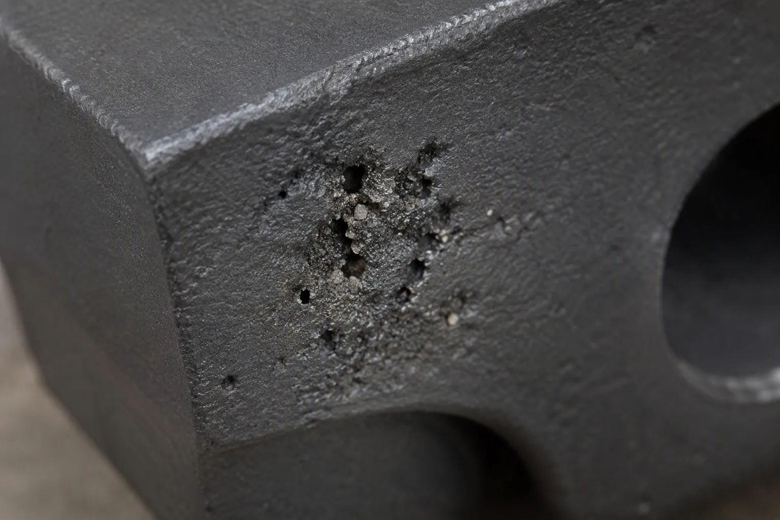
Visual identification: Irregular cavities or depressions on the casting surface partially or completely filled with molding sand. The sand grains are visible within the defect. Often associated with rough, irregular edges.
Root causes:
- Loose sand in the mold cavity not removed before mold closing
- Mold erosion during pouring — the metal stream washes sand from the mold wall
- Insufficient mold strength — the mold surface fails under the metallostatic pressure of the molten metal
- Core breakage during mold assembly or pouring
- Improper gating design — high-velocity metal impingement on mold walls
Prevention:
- Thoroughly clean mold cavities before closing — use compressed air and vacuum
- Design gating system to minimize turbulence and mold wall impingement — use tapered sprue, radiused runner bends, and multiple ingates
- Increase mold strength — use higher clay content, better compaction, or resin-bonded sand
- Apply mold wash (refractory coating) to improve surface strength
- Use ceramic foam filters in the gating system to capture sand and slag particles
Repair feasibility: Surface sand inclusions on machined surfaces are removed during machining (if within the machining allowance). Sand inclusions on as-cast surfaces can be ground out if the resulting depression is acceptable. Deep sand inclusions are not repairable — the casting is scrapped.
1.4 Scabs and Expansion Defects
Visual identification: Raised, rough, flaky patches on the casting surface where a thin layer of metal has separated from the main casting body. Scabs appear as surface crusts partially attached to the casting. Rattails are fine, shallow surface cracks or veins.
Root causes:
- Silica sand expansion — silica undergoes a rapid volume expansion (~5.5%) at 573 °C (alpha-to-beta quartz transformation), causing the mold surface to buckle
- High pouring temperature — intensifies sand expansion
- Insufficient mold permeability — mold gases cannot escape, pressurizing the mold cavity
- Clay-bonded sand with excessive moisture — steam generation causes surface spalling
Prevention:
- Use sand with lower thermal expansion — chromite sand, zircon sand, or silica sand with organic additives that burn out to create expansion buffer space
- Increase clay or binder content to improve hot strength
- Reduce pouring temperature where metallurgically acceptable
- Improve mold venting
- Use mold wash coatings that resist metal penetration
Repair feasibility: Superficial scabs can be ground flush. Scabs that leave depressions exceeding dimensional tolerances generally result in scrapped castings.
1.5 Metal Penetration and Burn-On
Visual identification: Metal or metal oxides penetrating between sand grains at the mold surface, resulting in a rough, sand-impregnated surface. After shot blasting, the surface appears granular with a "sandpaper" texture. Burn-on is a chemical reaction between metal oxides and silica sand forming a strongly adherent layer of iron silicate (fayalite).
Root causes:
- Excessive pouring temperature or metallostatic head — molten metal penetrates between sand grains
- Coarse sand grain size — larger intergranular voids
- Low mold density — inadequate compaction leaves open porosity at the mold surface
- Absence of mold wash — no barrier between metal and sand
- Reactive alloys (high-manganese steels, stainless steels) form low-melting-point silicates that wet the sand surface
Prevention:
- Use finer sand grain size (AFS GFN 50–80 for steel)
- Increase mold compaction
- Apply refractory mold wash (zircon, chromite, or alumina-based for steel; graphite-based for iron)
- Reduce pouring temperature
- For manganese steel and stainless steel: use chromite or zircon facing sand — these are chemically inert and do not react with the molten metal
Repair feasibility: Minor burn-on is removed by extended shot blasting. Heavy metal penetration that leaves surface depressions after cleaning may require grinding — acceptable if dimensions are maintained. Deep penetration is not repairable.
Part 2: Internal Defects
Internal defects are not visible from the surface and require volumetric NDT (UT, RT) or destructive sectioning for detection.
2.1 Shrinkage Porosity
Shrinkage porosity is the most common internal defect in steel castings. It occurs because metals contract during solidification — the volume decrease must be compensated by a continuous supply of molten metal from risers. When the feeding path is interrupted or the riser is inadequately sized, shrinkage cavities form.
Macro-Shrinkage (Shrinkage Cavity)
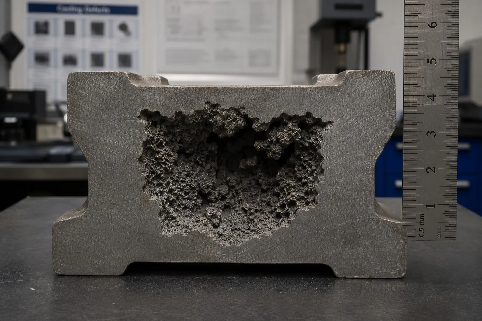
Visual identification (after sectioning or RT): Large, irregular cavities with rough, dendritic internal surfaces. The cavity walls show the characteristic tree-like (dendritic) structure of metal that solidified in contact with a void. Located at the last areas to solidify — typically at the geometric center of heavy sections, at section junctions, or isolated from riser feeding.
Root causes:
- Inadequate riser size — the riser solidifies before it has fully fed the casting
- Riser placement — the riser is not positioned at the heaviest section (last to freeze)
- Poor directional solidification — thinner sections solidify first and block the feeding path to thicker sections
- Excessive pouring temperature — increases the total solidification shrinkage
- Insufficient riser insulation (exothermic or insulating sleeves not used)
Prevention:
- Design the casting with directional solidification — sections should increase in thickness toward the riser
- Size risers using modulus-based calculation: riser modulus ≥ 1.2 × casting section modulus
- Use exothermic or insulating riser sleeves to extend riser solidification time
- Add chills to accelerate cooling of heavy sections, reversing the thermal gradient
- Simulation software (MAGMASOFT, ProCAST) to verify riser adequacy before pattern fabrication
Repair feasibility: Weld-repairable if the cavity is accessible from the surface (machined surface or ground access). Internal cavities not accessible from any surface cannot be repaired — the casting is scrapped.
Micro-Shrinkage (Microporosity)
Visual identification: A spongy, fine network of interconnected micro-voids visible on machined surfaces or in radiographs. On RT film, appears as a cloudy, mottled region rather than a discrete cavity. Often concentrated at section centers and junctions.
Root causes:
- Wide solidification range alloys (carbon steels with high carbon equivalent, stainless steels) — the mushy zone is extensive, making progressive feeding difficult
- Inadequate thermal gradient at the solidification front
- Gas evolution during solidification exacerbates micro-shrinkage (combined gas-shrinkage porosity)
Prevention:
- Reduce pouring temperature to increase the thermal gradient
- Add chills to steepen the temperature gradient at critical locations
- Use hot topping compounds in risers
- For stainless steel: optimize chemistry within specification for narrower solidification range
- Vacuum degassing or argon purging to reduce dissolved gas content
Repair feasibility: Localized micro-shrinkage on machined surfaces can be weld-repaired. Extensive micro-shrinkage throughout the casting is not repairable. For pressure-containing components, any micro-shrinkage in pressure boundary walls is typically cause for rejection.
2.2 Gas Porosity
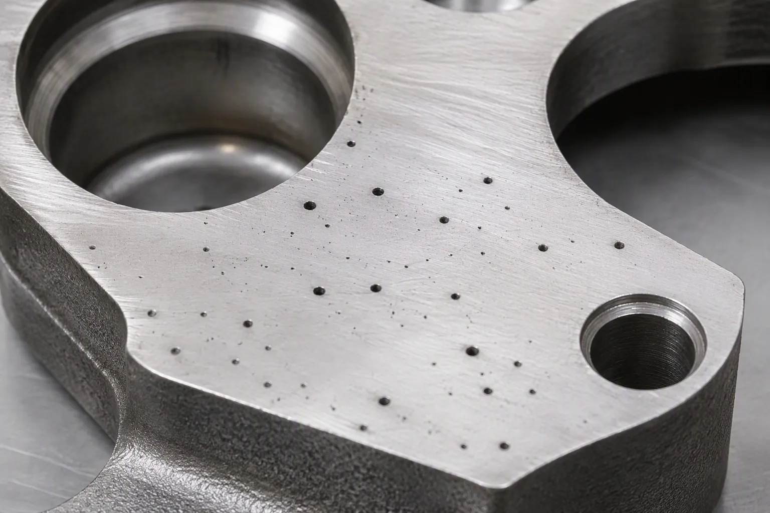
Visual identification: Smooth-walled, spherical or elongated cavities, typically 0.5–5 mm in diameter. Unlike shrinkage cavities (rough, dendritic walls), gas pores have smooth internal surfaces. They can be isolated or clustered. On machined surfaces, they appear as small, shiny holes.
Root causes — three gas sources:
- Dissolved gases: Hydrogen and nitrogen dissolved in the molten metal come out of solution during solidification (solubility decreases with temperature)
- Reaction gases: Chemical reactions in the mold — moisture in molding sand decomposes to hydrogen and oxygen; core binders decompose during pouring
- Entrapped gases: Air or mold gases mechanically trapped in the metal during turbulent pouring
Specific causes by gas type:
| Gas |
Source |
Characteristic Appearance |
| Hydrogen |
Wet furnace charge, wet refractories, humid molding sand, damp ferroalloys |
Small, bright, spherical pores; often in clusters |
| Nitrogen |
High-nitrogen ferroalloys, resin binder decomposition, air aspiration during pouring |
Irregular, elongated pores; often associated with nitride precipitates |
| Oxygen (reaction) |
Steam from mold moisture reacting with carbon or aluminum in the steel |
Irregular pores with oxide film lining; often near the casting surface |
| Entrapped air |
Turbulent pouring, gating system design, core gas evolution |
Larger, irregular pores; often at the top of the casting or at flow path terminations |
Prevention:
- Dry all furnace charge materials, refractories, ladles, and ferroalloys before use
- Control molding sand moisture content (3–5% for green sand)
- Adequately vent cores to allow binder decomposition gases to escape
- Degas molten steel with argon purging or vacuum treatment (for critical applications)
- Design gating system for non-turbulent flow (pressurized gating)
- Pour at the minimum temperature that fills the mold
- Use calcium treatment or aluminum deoxidation to tie up dissolved oxygen
Repair feasibility: Isolated surface-connected gas pores can be weld-repaired with qualified procedures. Subsurface gas porosity clusters are not repairable. For pressure-containing components, any through-wall gas porosity is cause for rejection.
2.3 Slag Inclusions
Visual identification: Irregular, non-metallic inclusions visible on machined surfaces or in radiographs. On RT film, slag inclusions appear as irregular dark regions (less dense than the surrounding metal). On machined surfaces, they appear as dark gray or black non-metallic patches, often with a glassy appearance.
Root causes:
- Inadequate slag removal from the ladle before pouring
- Slag entrapment during pouring — slag floating on the metal surface enters the mold
- Gating system does not trap slag effectively — no slag trap, whirl gate, or ceramic foam filter
- Reoxidation during pouring — exposure to air forms new oxide inclusions
- Refractory erosion — ladle or furnace refractory particles enter the metal
Prevention:
- Thorough slag skimming from the ladle before pouring
- Use bottom-pour ladles (metal drawn from below the slag layer)
- Incorporate ceramic foam filters in the gating system — 10 PPI (pores per inch) for steel, 20–30 PPI for iron
- Design gating system with slag traps — extended runner with weir, whirl gate, or spin trap
- Pour with a consistent, full stream — avoid interrupted pouring that introduces air
- Maintain ladle refractories in good condition
Repair feasibility: Surface slag inclusions on machined surfaces are removed during machining if they are shallow. Deep slag inclusions are not repairable. Slag inclusions in pressure boundary walls are cause for rejection.
Part 3: Dimensional Defects
Dimensional defects affect the part's geometry, making it impossible to meet drawing tolerances — regardless of internal soundness.
3.1 Misruns
Visual identification: The casting is incomplete — metal did not completely fill the mold cavity. Edges and thin sections are rounded; sharp corners are not formed. The defect occurs at the farthest point from the ingates.
Root causes:
- Pouring temperature too low — metal viscosity increases and fluidity decreases
- Pouring speed too slow — metal cools before reaching the extremities
- Thin sections below the minimum castable wall thickness for the alloy
- Inadequate gating — metal flow path too long for the available superheat
- Insufficient mold venting — back pressure prevents cavity filling
Prevention:
- Increase pouring temperature by 30–80 °C
- Increase pouring speed; use larger sprue and runner cross-sections
- Redesign thin sections — increase wall thickness to at least the process minimum
- Add additional ingates to reduce flow path length
- Improve mold venting with vent wires or permeable vent plugs
Repair feasibility: Not repairable. The casting is scrapped.
3.2 Warpage and Distortion
Visual identification: The casting is bent, twisted, or non-planar compared to the drawing geometry. Detectable by placing the casting on a surface plate and measuring gaps, or by CMM dimensional inspection. Distortion may not be visually obvious but causes features to be out of position or parallelism.
Root causes:
- Non-uniform cooling — different sections cool at different rates, creating thermal stresses that cause permanent deformation
- Inadequate stress relief before machining — residual stresses relax during metal removal, causing the casting to warp
- Improper heat treatment support — castings sag or distort under their own weight at elevated temperature if not properly supported
- Rapid quenching — thermal shock causes differential contraction
Prevention:
- Stress-relieve immediately after shakeout — do not allow castings to cool fully before stress relief
- Support castings properly in heat treatment furnaces — use support fixtures that maintain critical dimensions
- Use polymer or oil quench instead of water for distortion-prone shapes
- Straighten castings after heat treatment (press straightening at temperature for steel; cold straightening for ductile iron)
- For parts requiring high flatness: rough machine, stress-relieve, then finish machine
Repair feasibility: Minor distortion can be corrected by press straightening (at temperature for steel, cold for ductile iron up to ~2% plastic strain). Severe distortion in complex castings is often irrecoverable — the casting is scrapped.
3.3 Core Shift
Visual identification: Internal features (bores, passages, wall thicknesses) are offset from their intended positions. On RT or after sectioning, the core is visibly shifted. External indications: wall thickness variation when measured with UT thickness gauging.
Root causes:
- Inadequate core print design — core not securely located in the mold
- Core prints too small — insufficient bearing surface to resist buoyancy and metal flow forces
- Core assembled incorrectly during mold closing
- Mold halves misaligned during closing (related defect: mold shift / mismatch)
Prevention:
- Design core prints with sufficient length and cross-section — minimum 1.5× core diameter for horizontal cores
- Use chaplets (metal supports) to hold cores in position during pouring
- Use core assembly jigs and gauges to verify core placement before mold closing
- Use mold closing pins and bushings for positive mold alignment
- Specify core shift tolerance on the casting drawing to establish acceptable limits with the foundry
Repair feasibility: Not repairable if wall thickness is below minimum or internal features are out of position. Sometimes acceptable if wall thickness remains above minimum and the feature offset does not affect function — requires engineering disposition.
3.4 Mismatch (Mold Shift)
Visual identification: A visible step or offset at the parting line where the cope and drag halves of the mold were not aligned. The step is a constant offset across the entire parting line surface.
Root causes:
- Worn or loose mold closing pins and bushings
- Flask misalignment during mold handling and transport
- Pattern plate not centered in the flask
Prevention:
- Maintain mold closing pins and bushings — replace when wear exceeds 0.2 mm clearance
- Use mold closing guides and positive alignment systems
- Inspect first-off castings from each pattern for mismatch
Repair feasibility: Mismatch on machined surfaces is removed during machining (provided the mismatch is within the machining allowance). Mismatch on as-cast surfaces cannot be corrected — the casting is scrapped if the mismatch exceeds the dimensional tolerance.
Part 4: Material Defects
Material defects relate to the chemical composition, microstructure, or mechanical properties of the casting — even when the casting is dimensionally correct and internally sound.
4.1 Incorrect Chemical Composition
Visual identification: Not visually identifiable. Detected by spectrometer analysis (OES). May be indicated by unexpected hardness, machinability problems, or corrosion behavior.
Root causes:
- Incorrect furnace charge calculation
- Contamination of the furnace charge with wrong alloy scrap
- Ferroalloy addition errors — wrong type, wrong quantity, or addition at wrong time (oxidation loss)
- Carryover from previous heat — inadequate furnace cleaning between alloy changes
Prevention:
- Spectrometer verification of every heat before pouring — do not pour until chemistry is confirmed
- Use certified furnace charge materials with known composition
- Segregate scrap by alloy type — prevent mixing
- Clean furnace between incompatible alloy changes
- Retain a chill-cast spectrometer sample from every heat for independent verification
Repair feasibility: Not repairable. If detected before pouring, the heat can be corrected by alloy additions (subject to time and temperature constraints). Once poured, a casting with incorrect chemistry is scrapped.
At Dandong City Pengxin Machinery Co., Ltd., every heat is verified by optical emission spectrometer before pouring, with retained samples archived for independent verification. This front-end quality gate eliminates the most expensive defect of all: discovering wrong alloy chemistry after casting, machining, and inspection.
4.2 Hard Spots (Chilled Iron, Inverse Chill)
Visual identification: Localized areas of extreme hardness — typically 300–500 HB in an iron casting expected to be 150–200 HB. Visible on machined surfaces as bright, shiny spots where the cutting tool struggled. In gray iron, hard spots appear white on the fracture surface (cementite/white iron) rather than gray.
Root causes:
- Localized rapid cooling — thin sections, corners, or areas in contact with chills cool too fast, forming cementite instead of graphite
- Incorrect inoculant practice — insufficient or non-uniform inoculation allows carbide-stabilizing elements (Cr, V, Mo) to promote chill formation
- Excessive carbide-stabilizing elements (Cr, V, Ti, B) in the iron chemistry
- In ductile iron: magnesium treatment issues leading to carbide formation at cell boundaries
Prevention:
- Uniform inoculation with correct ferro-silicon inoculant grade and quantity (0.2–0.5% for gray iron; 0.3–0.6% for ductile iron)
- Control carbide-stabilizing elements in the charge — minimize Cr, V, Ti unless deliberately alloyed
- Increase silicon content (moves the iron toward graphitization)
- Reduce cooling rate — use insulating sleeves, avoid excessive chill placement
Repair feasibility: Hard spots causing machining difficulties can sometimes be softened by subcritical annealing (650–700 °C for gray iron, 700–760 °C for ductile iron). If annealing is unsuccessful or not permitted, the casting is scrapped.
4.3 Non-Conforming Mechanical Properties
Visual identification: Not visually identifiable. Detected by tensile, hardness, or impact testing. May manifest as premature failure in service if not caught during quality inspection.
Root causes:
- Incorrect heat treatment — wrong temperature, insufficient holding time, incorrect cooling rate
- Incorrect chemistry — carbon, manganese, or alloy content outside specification
- Test bar not representative — test bar poured separately and cooled differently from the casting
- Decarburization during heat treatment — surface carbon loss in an oxidizing atmosphere
Prevention:
- Verify heat treatment furnace calibration (temperature uniformity survey every 6 months)
- Record furnace charts for every heat treatment cycle — verify that the specified time-at-temperature was achieved
- Use integrally cast test bars (attached to the casting and cooled with it) for critical applications
- Use controlled atmosphere or vacuum heat treatment to prevent decarburization
- Perform hardness testing on every casting as a rapid screening test
Repair feasibility: If the deficiency is limited to hardness, re-heat-treating the casting may correct the properties. If the root cause is incorrect chemistry, the casting is irreparable.
Part 5: Defect Prevention — A Systematic Approach
5.1 The Prevention Hierarchy
| Level |
Strategy |
Effectiveness |
| 1. Design |
Design the part for castability — uniform sections, adequate fillets, appropriate draft |
Prevents 40–50% of defects |
| 2. Simulation |
Casting process simulation (MAGMASOFT, ProCAST) to validate gating and riser design |
Prevents 20–30% of defects |
| 3. Process control |
Standardized melting, molding, pouring, and heat treatment procedures with documented parameters |
Prevents 15–20% of defects |
| 4. Inspection |
In-process and final inspection to detect defects before shipment |
Catches defects, does not prevent them |
5.2 The Corrective Action Loop
When a defect is detected, a professional foundry does not simply scrap the casting and pour another — it investigates:
- Identify the defect — classify by type, location, frequency
- Analyze the root cause — use metallographic sectioning, chemical analysis, process parameter review
- Implement corrective action — change the process parameter, pattern design, or material
- Verify effectiveness — inspect the next production batch; confirm the defect is eliminated or reduced within acceptable limits
- Document — record the defect, root cause, corrective action, and verification in the quality system
Foundries with mature quality systems — such as Dandong City Pengxin Machinery Co., Ltd. operating under ISO 9001 — maintain a documented non-conformance and corrective action system that drives continuous improvement across all casting processes.
Conclusion
Casting defects are not random events — they have specific, identifiable root causes and well-documented prevention strategies. The most expensive defect is the one that reaches the customer. The second most expensive is the one that recurs because the root cause was never addressed.
Key principles for managing casting quality:
- Design for castability — the single most effective defect prevention measure is designing the part with uniform sections, generous radii, and appropriate draft
- Verify before you pour — spectrometer analysis of every heat prevents chemistry-related defects that are completely irreparable
- Simulate before you cut steel — casting simulation identifies shrinkage, misrun, and hot tear risks before pattern fabrication
- Stress-relieve early — do not let castings cool to ambient before stress relief if distortion or cold cracking is a risk
- Inspect proportionally to risk — the NDT extent should match the consequence of failure: 100% MT/UT for pressure-containing and safety-critical castings; sampling inspection for non-critical parts
- Close the loop — every defect should trigger a corrective action investigation, not just a replacement casting
Concerned about casting quality for your next project? Dandong City Pengxin Machinery Co., Ltd. combines 65+ years of foundry experience with modern process simulation, in-house spectrometer analysis, multi-method NDT, and a documented ISO 9001 quality system. Contact us to discuss your quality requirements.
 Hot News
 EN
EN