Meta Description: A technical guide to exhaust manifold casting for automotive and turbocharger applications. Learn about SiMo ductile iron, cast stainless steel alternatives, thermal fatigue design, shell mold casting, CNC machining of flanges, and high-temperature quality testing.
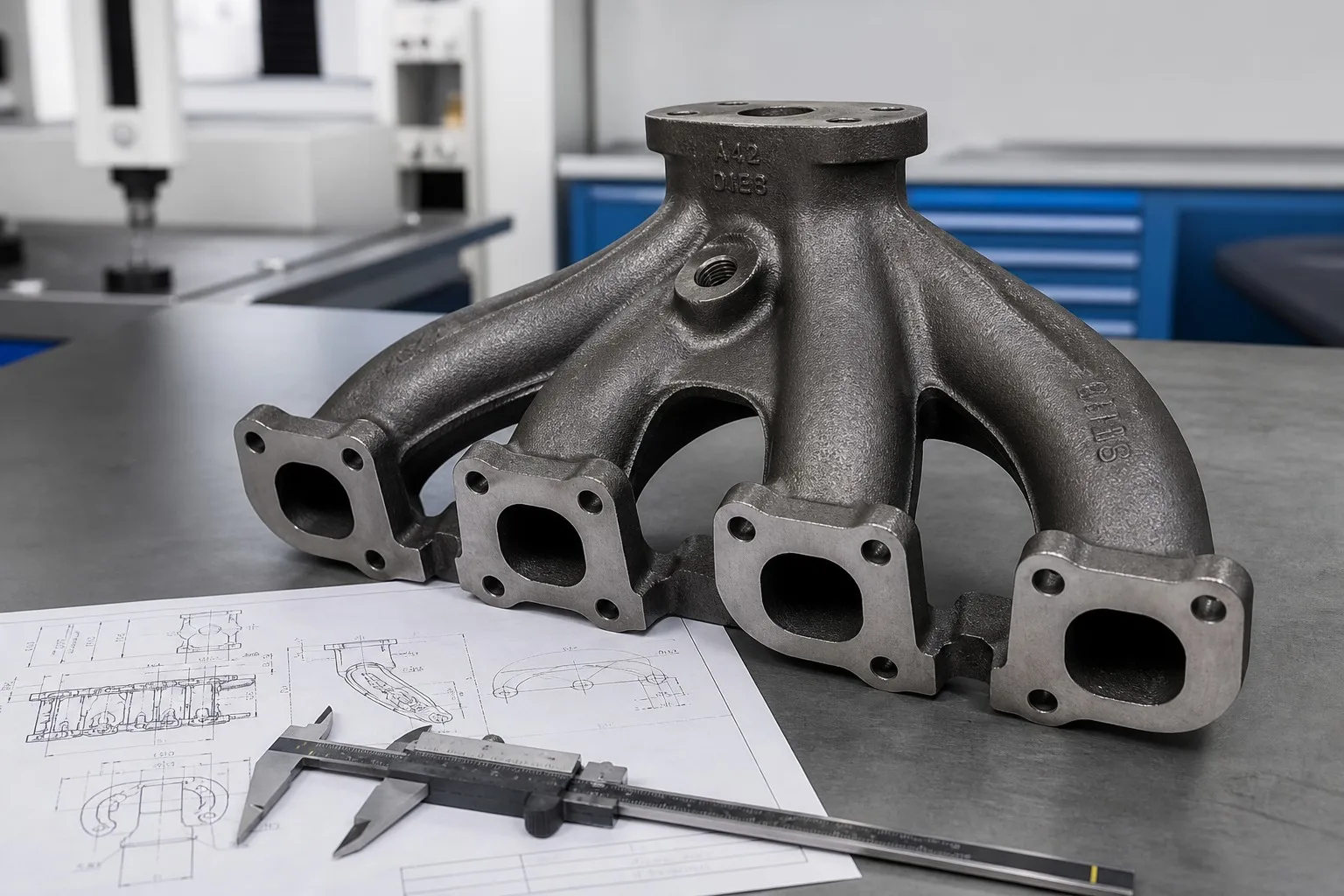
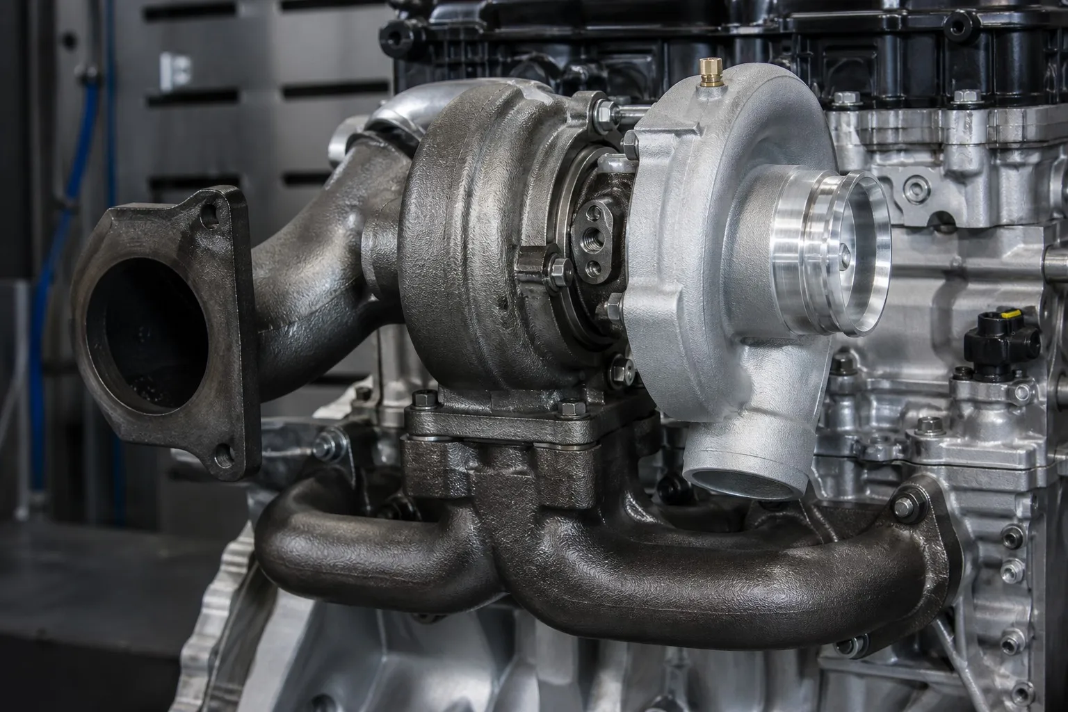
The exhaust manifold is one of the most demanding cast components in any engine. It collects hot exhaust gas from multiple cylinders, channels it to the turbocharger or catalytic converter, and survives thermal cycling from cold start to 850 °C — thousands of times over the life of the vehicle. It must resist oxidation, thermal fatigue, vibration, and thermal shock while remaining dimensionally stable enough to keep every flange sealed.
This guide examines the engineering of exhaust manifold castings: service conditions, material selection (SiMo ductile iron and its alternatives), design principles, manufacturing processes, machining, and quality assurance.
| Load | Typical Value | Consequence |
|---|---|---|
| Peak exhaust temperature | 750-850 °C (petrol), up to 900 °C (turbo diesels) | Oxidation, scaling |
| Thermal cycle amplitude | 20 °C to 800 °C | Thermal fatigue, cracking |
| Cycle frequency | Thousands to hundreds of thousands | Low-cycle fatigue |
| Internal pressure pulses | 0.5-3 bar | Fatigue, flange leakage |
| Vibration | Engine order + road excitation | High-cycle fatigue |
| Corrosion | Exhaust condensate, road salt | Wall thinning |
The dominant failure mode is thermal fatigue: differential expansion between hot and cool sections generates strain, and repeated cycling drives crack initiation and growth. Material selection and design both aim to delay this process.
Silicon-molybdenum ductile iron (SiMo) is the industry standard for modern exhaust manifolds. Its combination of castability, high-temperature strength, oxidation resistance, and low cost has displaced gray iron and many steel designs.
Typical composition (SiMo 4.0/1.0):
| Element | Content |
|---|---|
| Carbon (C) | 3.0-3.6% |
| Silicon (Si) | 3.5-4.5% |
| Molybdenum (Mo) | 0.4-1.0% |
| Manganese (Mn) | 0.2-0.5% |
| Magnesium (Mg) | 0.03-0.06% (nodularizer) |
| Phosphorus (P) | < 0.04% |
| Sulfur (S) | < 0.02% |
Why SiMo works:
| Material | Max Continuous Temp | Advantages | Trade-offs |
|---|---|---|---|
| Gray iron (HT250, G20) | ~450 °C | Low cost, good castability | Poor thermal fatigue, oxidation |
| SiMo ductile iron | ~750-800 °C | Best cost-performance for modern engines | Weight; limited above 800 °C |
| SiMo+ (higher Si/Mo) | ~850 °C | Improved oxidation for high-output engines | Reduced ductility, machinability |
| Ni-Resist (GGG-Ni) | ~800 °C | Excellent oxidation and thermal fatigue | High cost (Ni), machining |
| Cast stainless (1.4848, 1.4837) | ~950 °C | Highest temperature capability | Cost, thermal expansion control |
| Fabricated stainless tube | ~950 °C | Lightweight, low thermal mass | Weld quality control, cost |
Selection logic: below 800 °C continuous service, SiMo ductile iron is almost always the right economic and technical choice; above it, SiMo+ or cast stainless steel is required.
| Section | Typical Design |
|---|---|
| Primary runners | 4-6 mm |
| Collector | 5-7 mm |
| Flanges | 10-16 mm (stiff) |
Thin, uniform walls minimize thermal gradients and the associated strain. Wall transitions must be gradual — an abrupt change from 4 mm to 10 mm creates a hot spot that initiates thermal fatigue cracks.
The manifold expands ~10-12 mm over a 600 mm length when heated to 800 °C. The mounting system (slotted bolt holes, springs, flexible joints at the turbo flange) must accommodate this expansion without inducing excessive stress in the manifold or the turbocharger.
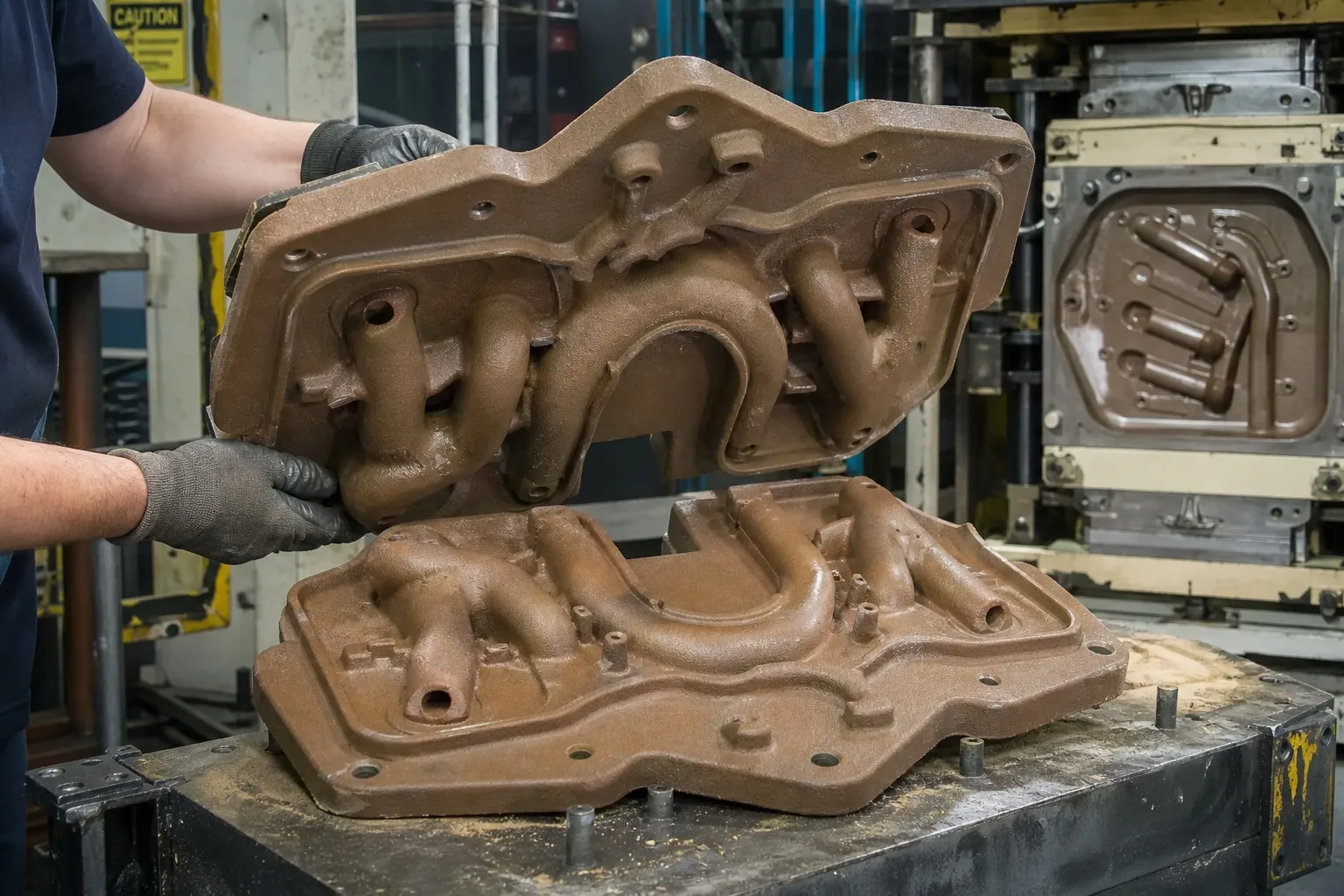
Most SiMo exhaust manifolds are produced by shell mold casting:
| Parameter | Typical Value |
|---|---|
| Molding process | Resin-coated sand shell, 6-12 mm shell thickness |
| Core system | Hot-box or cold-box cores for internal passages |
| Tolerance | ISO 8062 CT6-CT8 |
| Surface finish | Ra 6.3-12.5 µm |
| Machining allowance | 1.5-3 mm on flanges |
Shell molding gives the thin, accurate section control and smooth surfaces that runner geometry demands — and produces the high volumes typical of manifold programs with excellent repeatability.
| Treatment | Purpose | Typical Cycle |
|---|---|---|
| Stress relief (ferritizing) | Remove casting stress, stabilize ferrite | 550-600 °C, 2-4 h, furnace cool |
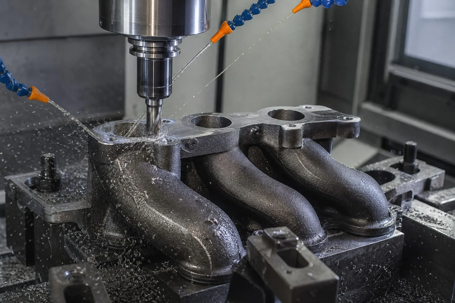
| Feature | Typical Requirement |
|---|---|
| Head flange face | Flatness 0.1 mm, Ra 3.2-6.3 µm |
| Exhaust port openings | Position ±0.2 mm to head bolt pattern |
| Turbocharger flange | Flatness 0.1 mm, surface perpendicular to bore |
| EGR ports | Diameter H8, position ±0.2 mm |
| Stud/threaded holes | Class 2A/2B |
| Gasket surfaces | Ra 3.2 µm, free of porosity after machining |
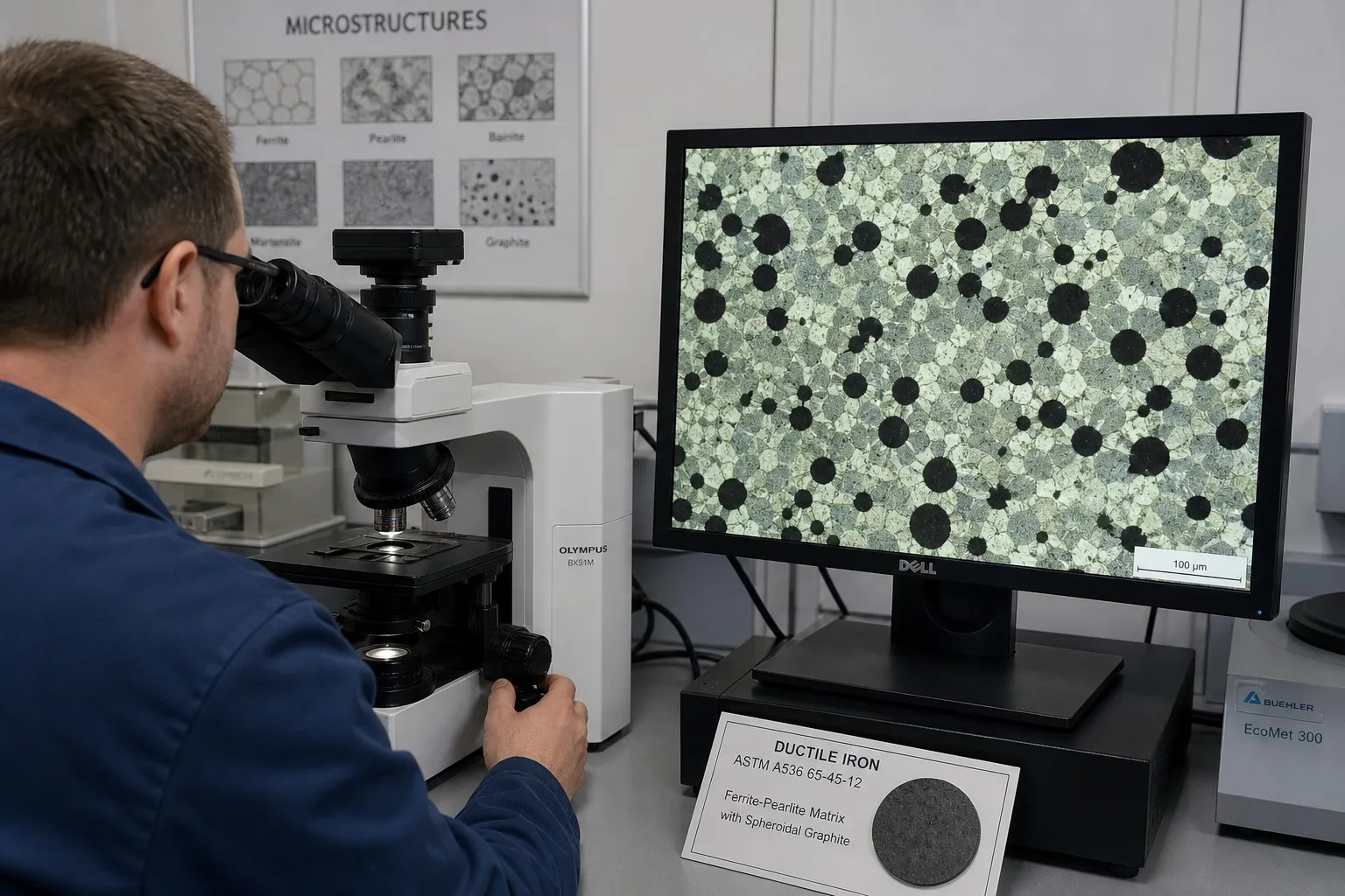
| Test | Purpose |
|---|---|
| Tensile test (room temp) | Verify strength: typically ≥ 450 MPa (SiMo) |
| Tensile test (elevated temp) | Verify high-temperature capability per spec |
| Hardness (HB) | Consistency check per heat |
| Nodularity evaluation | Graphite structure per ASTM A247 / ISO 945 |
| Chemical analysis | Full heat verification by spectrometer |
| Leak test | Internal passage integrity (air under water, or pressure decay) |
| Failure | Mechanism | Prevention |
|---|---|---|
| Thermal fatigue cracking | Cyclic plastic strain at hot spots | Uniform thin walls, generous radii, ferrite structure |
| Oxidation / scaling | Surface oxidation at high temp | SiMo chemistry, coating (e.g., aluminizing) |
| Flange warpage | Differential cooling in thick sections | Symmetrical design, stress relief |
| Creep relaxation | Long-term high-temperature loading | Mo content, design margins |
| Vibration fatigue | Engine excitation resonance | Stiffening ribs, validated natural frequency |
| Capability | Why It Matters |
|---|---|
| SiMo metallurgy experience | The grade is unforgiving — chemistry control is everything |
| Shell mold capability | Required for thin-section, high-volume manifolds |
| In-house CNC machining | Flange accuracy is machined, not cast |
| Leak and NDT testing | Turbo-flange integrity is safety-critical |
| PPAP documentation | Required for OEM and tier-1 programs |
| Casting simulation | Validates gating and feeding before tooling |
The exhaust manifold is a textbook example of how casting metallurgy and mechanical design work together. SiMo ductile iron — a material developed specifically for this application — gives engine builders a castable, affordable, high-temperature solution that has largely replaced gray iron and steel in modern engines. But the material only performs when the chemistry, casting process, heat treatment, and machining are all controlled to a high standard.
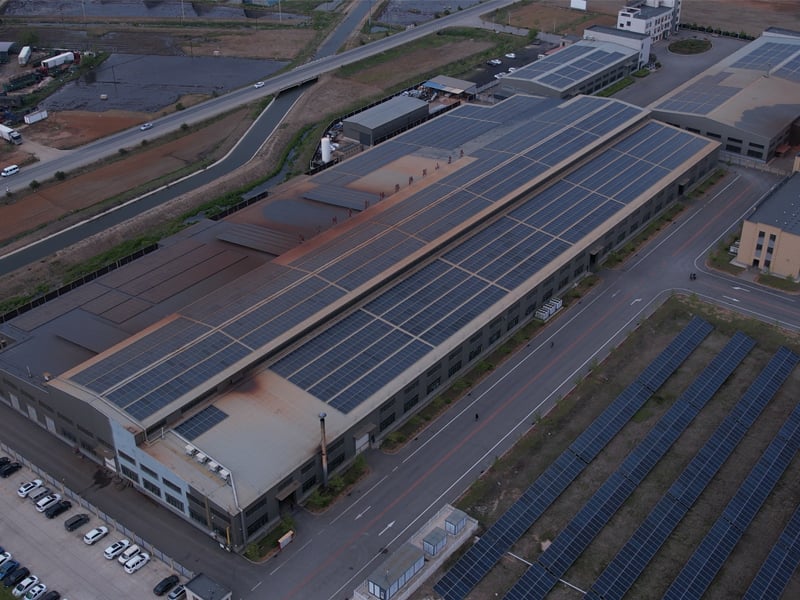
Dandong City Pengxin Machinery Co., Ltd. manufactures exhaust manifolds and turbocharger components in SiMo ductile iron, cast stainless steel, and Ni-Resist grades — with shell mold casting, full metallurgical testing, CNC machining of flanges and mounting faces, and leak/NDT verification under one ISO 9001 quality system. Our manifolds serve commercial vehicles, agricultural machinery, and performance aftermarket programs across global markets.
If you are developing a new manifold program or re-sourcing an existing part, contact us with your drawing and service conditions — our engineers will validate the material grade, casting design, and machining requirements before tooling begins.
Dandong City Pengxin Machinery Co., Ltd. — Heavy Castings and Precision Machining, Since 1958.
 Hot News
2026-10-16
2026-10-09
2026-10-02
2026-09-25
2026-09-18
2026-09-11

Dandong City Pengxin Machinery was founded in 1958, is a set of casting, machining and assembly as one of the private enterprises.
Wangjiapu Group, Xinan Village, Qianyang Town, Donggang City, Dandong City, Liaoning Province, China
Copyright © Dandong City Pengxin Machinery Co.,Ltd. All Rights Reserved Privacy Policy Blog
 EN
EN